The circuit which contains only inductance (L) and not any other quantities like resistance and capacitance in the circuit is called a Pure inductive circuit. In this type of circuit, the current lags behind the voltage by an angle of 90 degrees.
Contents:
- Explanation and Derivation of Inductive Circuit
- Phasor Diagram and Power Curve of Inductive Circuit
- Power in Pure Inductive Circuit
The inductor is a type of coil which reserves electrical energy in the magnetic field when the current flow through it. The inductor is made up of wire which is wound in the form of a coil. When the current flowing through inductor changes then time-varying magnetic field causes emf which obstruct the flow of current.The inductance is measured in Henry.The opposition of flow of current is known as the inductive reactance.
Explanation and Derivation of Inductive Circuit
The circuit containing pure inductance is shown below:

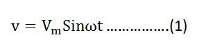
Let the alternating voltage applied to the circuit is given by the equation:
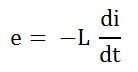
As a result, an alternating current i flows through the inductance which induces an emf in it. The equation is shown below:
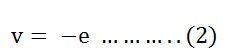
The emf which is induced in the circuit is equal and opposite to the applied voltage. Hence, the equation becomes,
Putting the value of e in equation (2) we will get the equation as
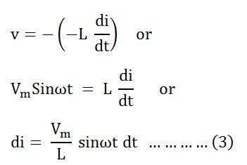
Integrating both sides of the equation (3), we will get
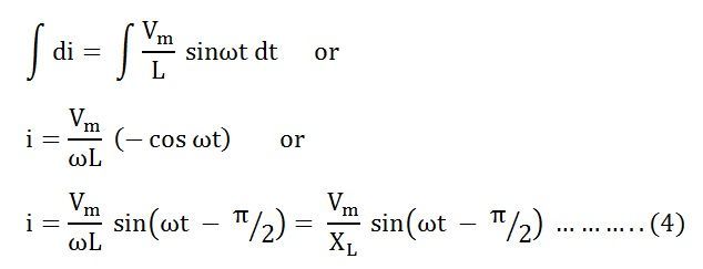 where, XL = ω L is the opposition offered to the flow of alternating current by a pure inductance and is called inductive reactance.
The value of current will be maximum when sin (ωt – π/2) = 1
Therefore,
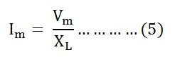
Substituting this value in Im from the equation (5) and putting it in equation (4) we will get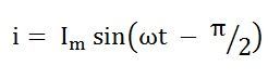
Phasor Diagram and Power Curve of Inductive Circuit
The current in the pure inductive AC circuit lags the voltage by 90 degrees. The waveform, power curve and phasor diagram of a purely inductive circuit is shown below
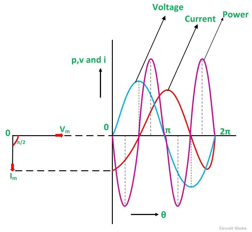
The voltage, current and power waveform are shown in blue, red and pink colours respectively. When the values of voltage and current are at its peak as a positive value, the power is also positive and similarly, when the voltage and current give negative waveform the power will also become negative. This is because of the phase difference between voltage and current.
When the voltage drops, the value of the current changes. When the value of current is at its maximum or peak value of the voltage at that instance of time will be zero, and therefore, the voltage and current are out of phase with each other by an angle of 90 degrees.
The phasor diagram is also shown on the left-hand side of the waveform where current (Im) lag voltage (Vm) by an angle of π/2.
Power in Pure Inductive Circuit
Instantaneous power in the inductive circuit is given by
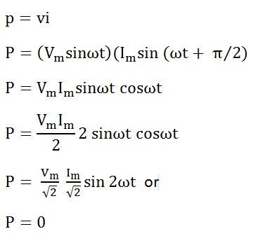
Hence, the average power consumed in a purely inductive circuit is zero.
The average power in one alteration, i.e., in a half cycle is zero, as the negative and positive loop is under power curve is the same.
In the purely inductive circuit, during the first quarter cycle, the power supplied by the source, is stored in the magnetic field set up around the coil. In the next quarter cycle, the magnetic field diminishes and the power that was stored in the first quarter cycle is returned to the source.
This process continues in every cycle, and thus, no power is consumed in the circuit.
Thanks it was very helpful
What happened in reactive power
Very helpful thanks
Thanks for explaning very good
Thank you
Why i=ImSin(wt+π/2). ????????
Since you prove that I=ImSin(wt-π/2)
As given i=Imsin(theta – 90) then why in calculating power you put i=Imsin(theta+90) please tell me
good article
this was really helpful…
truly grateful
Thank you for the detailed explanation..
thanks for detailed explanation 👍 😀👌
Thanks