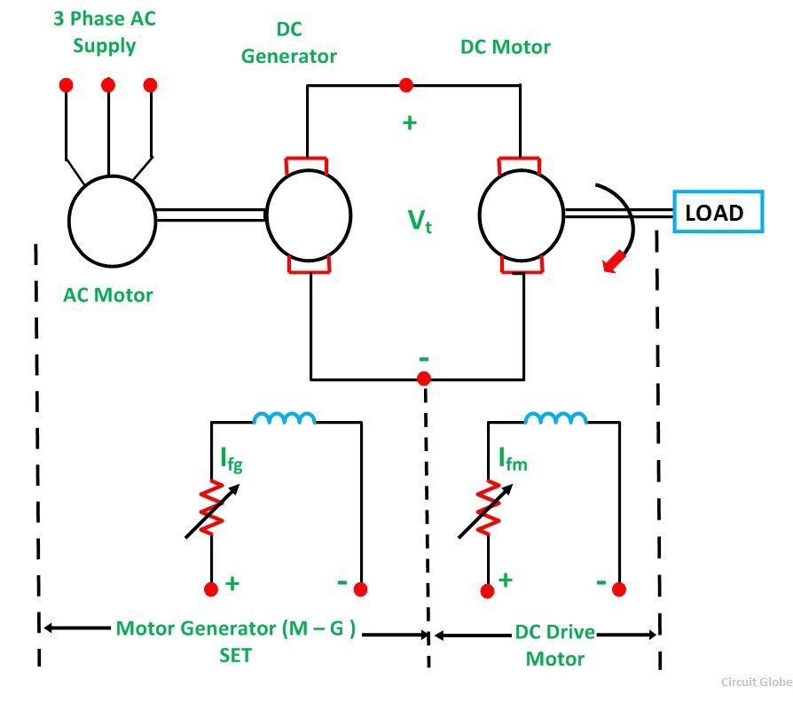
Ward Leonard Method of speed control is achieved by varying the applied voltage to the armature. This method was introduced in 1891. The connection diagram of the Ward Leonard method of speed control of a DC shunt motor is shown in the figure below.
 Contents
- Torque and Power Characteristic
- Advantages of Ward Leonard Drives
- Drawbacks of Classical Ward Leonard System
- Applications of Ward Leonard Drives
- Solid State Control or Static Ward Leonard System
In the above system, M is the main DC motor whose speed is to be controlled, and G is a separately excited DC generator. The generator G is driven by a 3 phase driving motor which may be an induction motor or a synchronous motor.
The combination of an AC driving motor and the DC generator is called the Motor-Generator (M-G) set.
The voltage of the generator is changed by changing the generator field current. This voltage when directly applied to the armature of the main DC motor, the speed of the motor M changes. The motor field current Ifm is kept constant so that the motor field flux ϕm also remains constant. While the speed of the motor is controlled, the motor armature current Ia is kept equal to its rated value.
The generated field current Ifg is varied such that the armature voltage Vt changes from zero to its rated value. The speed will change from zero to the base speed. Since the speed control is carried out with the rated current Ia and with the constant motor field flux, a constant torque is directly proportional to the armature current, and field flux up to rated speed is obtained. The product of torque and speed is known as power, and it is proportional to speed.
Thus, with the increase in power, speed increases automatically.
The Torque and Power Characteristic is shown in the figure below:
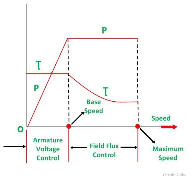
Hence, with the armature voltage control method, constant torque and variable power drive are obtained from speed below the base speed. The field flux control method is used when the speed is above the base speed. In this mode of operation, the armature current is maintained constant at its rated value, and the generator voltage Vt is kept constant.
The motor field current is decreased and as a result, the motor field flux also decreases. This means that the field is weakened to obtain higher speed. Since VtIa and EIa remain constant, the electromagnetic torque is directly proportional to the field flux ϕm and the armature current Ia.
Thus, if the field flux of the motor is decreased the torque decreases.
Therefore, the torque decreases, as the speed increases. Thus, in the field control mode, constant power and variable torque are obtained for speeds above the base speed. When the speed control over a wide range is required, a combination of armature voltage control and field flux control is used.
This combination permits the ratio of maximum to minimum speed available speeds to be 20 to 40. For closed-loop control, this range can be extended up to 200.
The driving motor can be induction or synchronous motor. An induction motor operates at a lagging power factor. The synchronous motor may be operated at a leading power factor by over-excitation of its field. Leading reactive power is generated by an over-excited synchronous motor. It compensates for the lagging reactive power taken by other inductive loads. Thus, the power factor is improved.
A slip ring induction motor is used as p prime mover when the load is heavy and intermittent. A flywheel is mounted on the shaft of the motor.
This scheme is known as Ward Leonard-Ilgener scheme. It prevents heavy fluctuations in supply current.
When the Synchronous motor is acting as a driving motor, the fluctuations cannot be reduced by mounting a flywheel on its shaft, because the synchronous motor always operates at a constant speed.
In another form of Ward Leonard drive, non-electrical prime movers can also be used to drive the DC generator.
For example – In DC electric locomotive, DC generator is driven by a diesel engine or a gas turbine and ship propulsion drives. In this system, Regenerative braking is not possible because energy cannot flow in the reverse direction in the prime mover.
Advantages of Ward Leonard Drives
The main advantages of the Ward Leonard drive are as follows:-
- Smooth speed control of DC motor over a wide range in both the direction is possible.
- It has an inherent braking capacity.
- The lagging reactive volt-amperes are compensated by using an overexcited synchronous motor as the drive and thus, the overall power factor improves.
- When the load is intermittent as in rolling mills, the drive motor is an induction motor with a flywheel mounted to smooth out the intermittent loading to a low value.
Drawbacks of Classical Ward Leonard System
The Ward Leonard system with rotating Motor Generator sets has following drawbacks:
- The initial cost of the system is high as there is a motor-generator set installed, of the same rating as that of the main DC motor.
- Larger size and weight.
- Requires large floor area
- Costly foundation
- Maintenance of the system is frequent.
- Higher losses.
- Lower efficiency.
- The drive produces more noise.
Applications of Ward Leonard Drives
The Ward Leonard drives are used where smooth speed control of the DC motors over a wide range in both the directions is required. Some of the examples are as follows:
- Rolling mills
- Elevators
- Cranes
- Paper mills
- Diesel-electric locomotives
- Mine hoists
Solid State Control or Static Ward Leonard System
Nowadays Static Ward Leonard system is mostly used. In this system, the rotating motor-generator (M-G) set is replaced by a solid-state converter to control the speed of the DC motor. Controlled Rectifiers and choppers are used as a converter.
In the case of an AC supply, controlled rectifiers are used to convert fixed AC supply voltage into a variable AC supply voltage. In the case of DC supply, choppers are used to obtain variable DC voltage from the fixed DC voltage.
very good information. Thanks
Very Good Explanation. Thanks
Very nicely explained. The concepts are totally cleared.
I could visualize the actual working of the system.