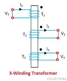
Definition: Sometimes in high rating transformer, the third winding is constructed in addition to the primary and the secondary windings. The third winding is called the tertiary winding, and because of the three windings, the transformer is called the three winding transformer.
The voltage ratings of all the three windings of the transformer are usually unequal.The primary winding has the highest voltage rating; the tertiary has the lowest voltage rating, and the secondary has the intermediate voltage rating.
The chief advantages of the three winding transformers is an economy of construction and their great efficiency. The schematic diagram of a three-phase transformer is shown in the figure below.
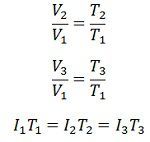
 For an ideal transformer,
 The most significant advantage of the third winding is are that the harmonic generated by the primary and secondary winding extinguish by the third winding. The third winding is connected in delta.
The voltage of the tertiary winding differs than the primary and secondary winding. Thus, it is used for supplying the power to the auxiliary appliances like the fan, tube light, etc. of the substations. The tertiary winding is used for following applications.
- The reactive power is supplied to the substations with the help of the tertiary winding.
- The tertiary winding reduces the impedance of the circuit so that the fault current easily passes to the ground.
- It is used for testing the high rating transformer.
Equivalent Circuit of a Three Winding Transformer
The equivalent circuit diagram of the three-phase transformer is shown in the figure. Consider the R1, R2 and R3 are the resistance and the X1, X2 and X3 are the impedance of their windings.
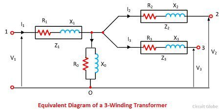 The V1, V2, V3 are the voltages and the I1, I2, I3 are current flows through their windings.
Determination of Parameters of Three-Windings Transformers
The parameters of the equivalent circuit can be determined from the open circuit and the three short-circuit tests.
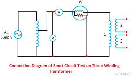
Short Circuit Test
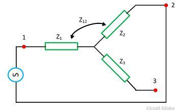
Consider the Z1, Z2 and Z3 are the impedances of the three winding transformers. These impedances are considered as the base for performing the short circuit test. For the short-circuit test, the two winding is short circuit and the third winding is kept open.
In the first step, consider the winding 1 and 2 are short-circuited. The low voltage winding is applied to the winding 1 due to which the full load current flows through the winding 2. The Z12 indicates the impedance of winding 1 and 2 and it measured as
 Equivalent resistance,
 Equivalent leakage reactance,
![]()
The Z12 is the series combination of Z1 and Z2 respectively,
![]()
 In the second step, the third winding is short-circuited with the second winding and the first winding is kept open. The low voltage source is applied across the third winding so that the full load current flows through the second winding. The Z23 represents the impedance of the winding 2 and 3 and the below equation expresses it
![]() In the third step, the second winding is opened and first and third winding are short-circuited. The low voltage is supplied to the third winding, and full load current flows through the first windings. The Z13 is the impedance of the first and third winding.
In the third step, the second winding is opened and first and third winding are short-circuited. The low voltage is supplied to the third winding, and full load current flows through the first windings. The Z13 is the impedance of the first and third winding.
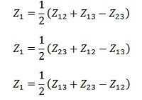
 Solving equation (1), (2) and (3) we get the leakage impedance Z1, Z2 and Z3 all referred to as primary,
 Open-Circuit Test
The open circuit test is carried out to determine the core loss, magnetising impedance and turn ratios. In open circuit test the voltmeter, ammeter and wattmeter are connected in low voltage winding. The secondary side is kept open, and the voltmeter is connected.
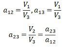
Since the high voltage side is opened the current drawn by the primary is no load current and I0 measured by the ammeter A. The magnetising impedance may be found by exciting current winding 1 with both winding 2 and 3 be open circuit. Then we have,
 The voltage regulation of a three-winding transformer is defined as the ratio of the magnitude of the actual kVA loading of the winding to the base kVA used in determining the network parameters.
Good explanation
how to calculate copper losses in 3 winding transformer?