Definition: Steady state stability is defined as the capability of an electric power system to maintain its initial condition after small interruption or to reach a condition very close to the initial one when the disturbance is still present.The steady state stability is very important in planning and designing of the power system, in developing special automatic control device, putting into operation new elements of the system, or modifying its new operating condition.
The estimation of steady state limit is important for power system analysis.The power system analysis includes the checking of an electrical power system in a specified steady state, the determination of its stability limits and qualitative estimation of the transient. It also estimates the choice of type of the excitation system and its controls, the modes of control, the parameter of the excitation and automation control system.
The selection of the stability is made by the requirements of the stability limit or quality of electrical energy under steady state condition or during the transient. The steady state limit refers to the maximum flow of power through a particular point without causing the loss of stability when the power is increased very gradually.
When all the machines in one part run together, then they are treated as one large machine connected at that point. Even, if the machines are not connected to the same bus bar and are separated by large reactance, they are also considered a large machine. The large system in a power system is always supposed to have a constant voltage and is treated as an infinite bus.
Consider a system consists a generator G, transmission line and a synchronous motor M in the form of a load.
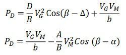
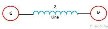 The expression shown below gives a power developed by a generator G and synchronous motor M.
 The expression below gives the maximum power generated by the generator G and synchronous motor M
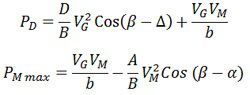 Where A, B, and D are the generalised constants of the two terminal machine. The above expression will give power in watts and per phase in case of voltage and are taken as the phase voltage in volts.
Reason for Unstable system
Consider a synchronous motor connected to an infinite busbar and running at a constant speed. The input power is equal to the power output plus losses. If the smallest increment of the shaft load is added to the motor, then the power of the motor increases and the input power of the motor remain unchanged. Thus, the net torque of the motor tending to retard it and its speed falls temporarily.
The retardation in torque reduces the motor speed, the phase angle between the internal voltage of the motor and the system voltage increase until the electrical power input is equal to the power output plus losses.
During the transient power interval, the electrical power input to the motor being less than the mechanical load, the excess power required is supplied by the stored energy in the rotating system. The motor oscillates around the equilibrium and may finally either comes to rest or may lost synchronism.The system also lost its stability, when the large load is applied or when the load is applied too suddenly on the machine.
The equation below shows the maximum power that the motor can develop. The value of load only can be obtained when the power angle (δ) = load angle (β). And the load may increase till this condition is reached. After this condition, if the load rises then the machine losses their synchronism and the over power required.
The excess power will come from the stored energy of the rotating system, and the speed goes down. Larger and larger the power become, smaller and smaller the angle will develop till the motor come to rest.
The difference between the motor and the generator power developed for any value of δ is equal to the line losses. If the resistance and shunt admittance of line are negligible, then we get the following expression for the power transferred between the alternator and motor.
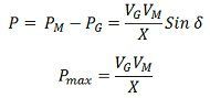 Where, X – line reactance
VG – voltage of generator
VM – voltage of motor
δ – Load Angle
PM – Power of motor
PG – Power of motor
Pmax – maximum power
Methods for Improving Steady State Limit
The maximum power transferred between an alternator, and a motor is directly proportional to the product of internal emf of the machines and inversely proportional to the line reactance. The steady state limit is increased because of the two reasons;
- By increasing the excitation of a generator or motor or both – The excitation increase the internal emf and consequently the maximum powered transferred between the two machines increases. Further with the increased value of internal EMFs, the load angle δ decreases.
- Reducing the transfer Reactance – The reactance is reduced by increasing the parallel line between the transmission points. The use of bundle conductor is the other method of reducing the reactance of the line. The reactance can also be decreased by using the capacitance in series with the line.
Series capacitor is only used in EHV lines to increase the power transfer and are more economical distance over 350 km.