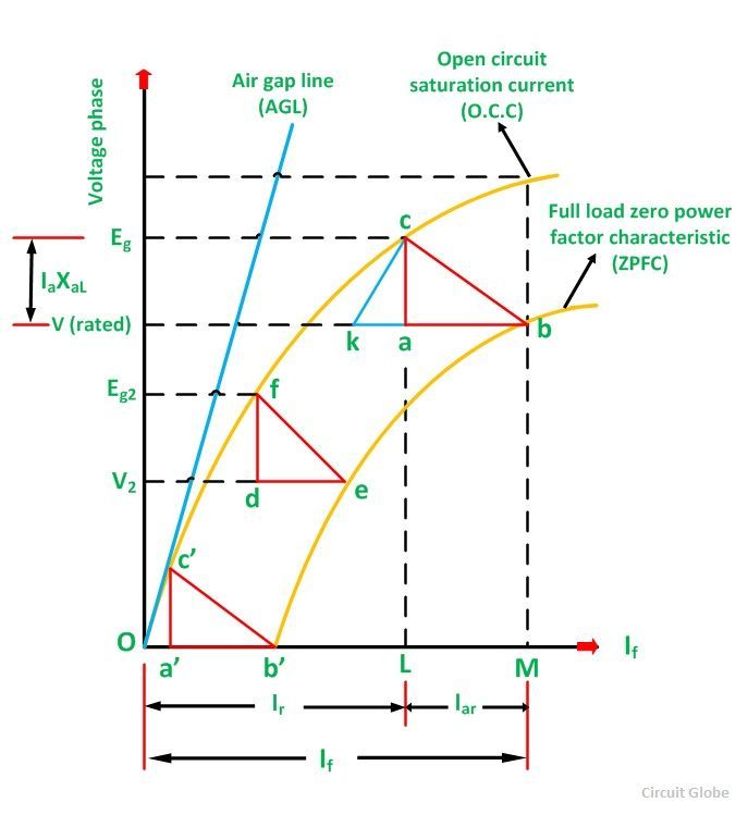
The Potier triangle determines the voltage regulation of the machines. This method depends on the separation of the leakage reactance of armature and their effects. The graph of the Potier triangle is shown in the figure below. The triangle formed by the vertices a, b, c has shown below in the figure is called Potier Triangle.
Contents:
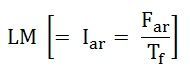
Consider a point B on the Zero Power Factor Curve corresponding to rated terminal voltage V and a field current of OM = If = Ff/Tf. If for this condition of operation the armature reaction MMF has a value expressed in equivalent field current will be given as:
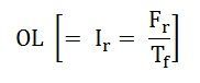
 Then the equivalent field current of the resultant MMF would be represented as shown below:
 This field current OL would result in a generated voltage Eg = Lc from the no-load saturation curve. Since for lagging zero power factor operation, the generated voltage will be:
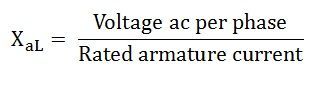
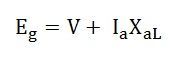 The vertical distance ac must be equal to the leakage reactance voltage DROP IaXaL where Ia is the rated armature current.
Therefore,
 For Zero Power Factor operation with the rated current at any other terminal voltage, such as V2. As the armature current is of the same value, both the Ia and XaL voltage and the armature MMF must be of the same value.
Therefore, for all the conditions of operation with rated armature current at zero lagging power factor, the Potier Triangle must be located between the terminal voltage V, a point on the ZPFC, and the corresponding Eg point on the O.C.C.
If the Potier triangle cab is moved downward so that the side ab is kept horizontal and b is kept on the ZPFC, the point c will move on the O.C.C. When the point b, reaches the point e, the Potier triangle cab will move on the position fde shown in the figure. The location of point f on the O.C.C will determine the voltage Eg2. When the point b, reaches the point b’, the Potier Triangle will be in the position c’a’b’. This is the limiting position that corresponds to short the circuit condition because the terminal voltage is zero at the point b’.
The initial part of the O.C.C is almost linear, another triangle Oc’b’is formed by the O.C.C. The hypotenuse of the Potier triangle and the baseline. A similar triangle such as ckb, can construct from the Potier triangle in any other location by drawing a line kc parallel to Oc’.
Steps for Construction of Potier Triangle on ZPFC
- Take a point b on the ZPFC preferably well upon the knee of the curve.
- Draw bk equal to b’O. (b’ is the point for zero voltage, full load current). Ob’ is the short circuit excitation Fsc.
- Through k draw, kc parallel to Oc’ to meet O.C.C in c.
- Drop the perpendicular ca on to bk.
- Then, to scale ca is the leakage reactance drop IaXaL and ab is the armature reaction MMF FaR or the field current IfaR equivalent to armature reaction MMF at rated current.
The effect of field leakage flux in combination with the armature leakage flux gives rise to an equivalent leakage reactance Xp, known as the Potier Reactance. It is greater than the armature leakage reactance.
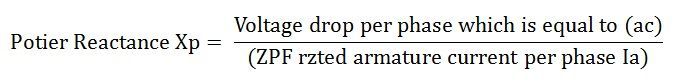
For cylindrical rotor machines, the Potier reactance Xp is approximately equal to the leakage reactance XaL. in salient pole machine, Xp may be as large as 3 times XaL.
Assumptions for Potier Triangle
The following assumptions are made in the Potier Triangle Method. They are as follows:-
- The armature resistance Ra is neglected.
- The O.C.C taken on no-load accurately represents the relation between MMF and Voltage on load.
- The leakage reactance voltage Ia XaL is independent of excitation.
- The armature reaction MMF is constant.
It is not necessary to plot the entire ZPFC for determining XaL and Fa, only two points b and b’ are sufficient. Point b corresponds to a field current which gives the rated terminal voltage while the ZPF load is adjusted to draw rated current. Point b’ corresponds to the short circuit condition (V = 0) on the machine. Thus, Ob’ is the field current required to circulate the short circuit current equal to the rated current.
Also See: Zero Power Factor Characteristics
I want more information in machines