The basic feature of Pole Amplitude Modulation (PAM) winding is the layout, which is irregular. The windings are divided into two parts. The two parts are either connected in series or parallel. The directions of current in the two halves are either the same or opposite. The process of the current reversal is equivalent to modulation and gives the different pole combinations.
The Pole Amplitude Modulation Technique is explained in this article with the help of an example. Let us considered that the MMF distribution in the air gap of a three-phase induction motor due to the stator winding carrying three-phase balanced currents can be written as shown below: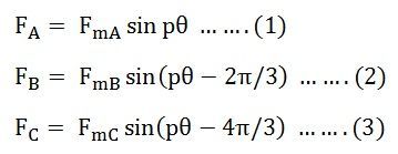
Where p is the number of pairs of poles and ? is the mechanical angle in radians.
In a three-phase induction motor, the number of turns in each phase winding are equal, and if the motor is supplied by a balanced three-phase current, the maximum values of mmfs in all the phases are the same.
If the three modulating waves are having an amplitude F but displaced from each other by 2π/3 radians are used to modulate the MMF waves. Then FmA, FmB and FmC can be written in equation forms as shown below.: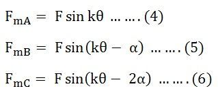
Where, F is a constant and k is the number of modulating cycles and α = ±2π/3
Substituting the value of equations (4) (5) and (6) in the equation (1) (2) and (3) respectively, we get the following equations shown below.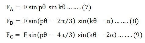
Equation (7) and (9) can be written as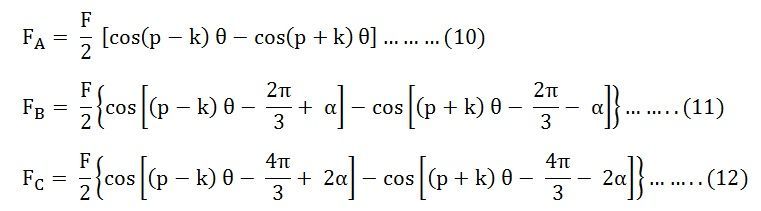
Thus, modulating the amplitude of the MMFS in a three-phase machine having a p pair of poles produces two sets of three-phase MMFS with (p-k) and (p+k) poles. The two sets of poles will produce torques in opposite directions. For obtaining a steady torque in one direction only, one of these pole pairs must be suppressed, and the other pair should be retained.
Two methods of connections are used to obtain the desired modulation. The first method is known as the Coil Inversion, and the other is known as Coil Inversion and Omission. In both methods, the windings of each phase are divided into two parts.
In the coil inversion method, the current through the other half of winding in each phase is reversed.
Figure (a) below shows the basic principle of pole amplitude modulation. The negative half cycle of the modulating wave reverses the polarities of the main poles 5, 6, 7, and 8. The MMF wave of a stator wound for eight poles and 2 poles modulating waves is shown in figure (b) below:
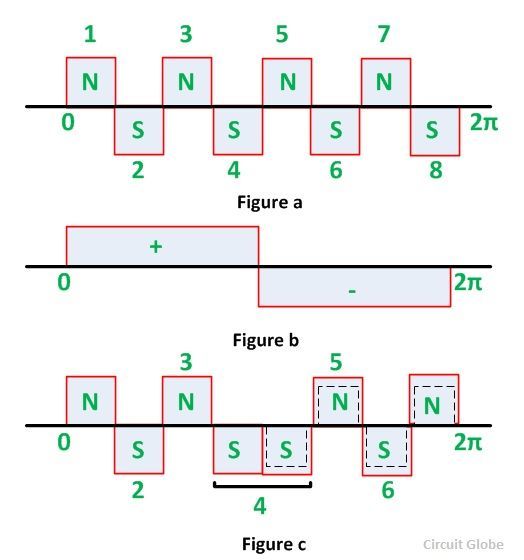
The reversed poles are shown by dotted lines. The above figure (c) shows that the resultant wave that the modulated wave has 6 poles.
In the second method of coil inversion and omission method, a section of the winding is omitted from each half and half of the remaining portion of the winding is reversed with respect to the first half.
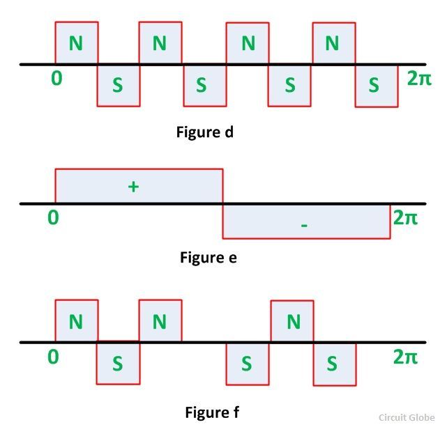
Figure (d) shows the MMF wave of a stator wound for eight poles. In figure (e) fourth and eighth coils are omitted whereas the fifth, sixth, and seventh coils are reversed with respect to the first three coils. Thus, the motor can run corresponding to 8 poles that were original and 6 poles that are modulated.
The three-phase machine can be connected in delta or star. By proper choice of series or parallel connections between coil groups of each phase and the star or delta connection between the phases, speed change can be obtained with constant torque operation, constant power operation, or variable torque operation.
This Pole Amplitude Modulation Technique is used in fan, blower, and pump drives.