Mesh Current Analysis Method is used to analyze and solve the electrical network having various sources or the circuit consisting of several meshes or loop with a voltage or current sources. It is also known as the Loop Current Method.
In the Mesh Current method, a distinct current is assumed in the loop and the polarities of drops in each element in the loop are determined by the assumed direction of loop current for that loop.
The unknown in mesh current analysis is the current in different meshes, and the law which is applicable to solve the circuit by the mesh current method is known as Kirchhoff’s Voltage Law (KVL) which states that –
In any closed circuit, the net voltage applied is equal to the sum of the product of current and resistance or in another word in any closed circuit, the sum of the voltage rise is equal to the sum of voltage drop, in the direction of current flow.
Contents:
KVL is already discussed in the topic ALSO SEE: Kirchhoff’s Current Law and Kirchhoff’s Voltage Law
Let us understand the Mesh Current method with the help of the circuit shown below
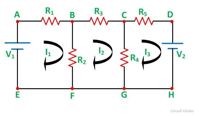 In the above network
- R1, R2, R3, R4 and R5 are the various resistances
- V1 and V2 are the voltage source
- I1 is the current flowing in the mesh ABFEA
- I2 is the current flowing in the mesh BCGFB
- I3 is the current flowing in the mesh CDHGC
The direction of the current is assumed in the clockwise for simplicity in solving the network.
Steps for Solving Network by Mesh Current Method
Considering the above circuit diagram, the following steps are given below to solve the circuit by the Mesh Current method.
Step 1 – First of all, identify the independent circuit meshes or loop.
.As there is three mesh in the circuit diagram shown above which are considering.
Step 2 – Assign a circulating current to each mesh as shown in circuit diagram where I1, I2 and I3 are flowing in each mesh.
It is preferable to assign the same direction of all the currents and in a clockwise direction for making the calculation easier.
Step 3 – Now, write the KVL equation for each mesh.
As there are three meshes in the circuit, there will be three KVL equations as shown below
Applying KVL in the mesh ABFEA
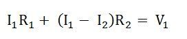
By rearranging the equation, we will get an equation (1)

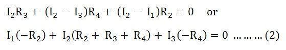
Applying KVL in the mesh BCGFB
 Applying KVL in the mesh CDHGC
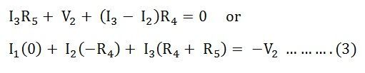
Step 4 – Now solve equations (1) (2) and (3) simultaneously to get the value of current I1, I2 and I3.
By knowing the mesh currents, we can determine the various voltages and currents in the circuit.
Matrix Form
The above circuit can be solved by the Matrix method also, as shown below
The above equations (1), (2) and (3) in matrix form can be expressed as
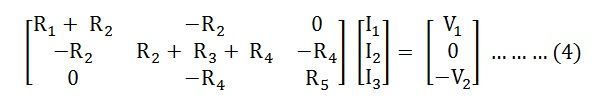 Thus, the equation (4) can be solved to get the values it the various currents.
It is seen from the equation (4) that the resistance matrix [R] is symmetric, i.e.
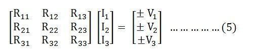
Equation (5) can be written as:
![]()
Where,
[R] is the mesh resistance
[I] is the column vector of mesh currents and
[V] is the column vector of the algebraic sum of all the source voltages around the mesh.
This is all about the mesh current analysis method.