The three-phase induction motor is a preferable type of motor. It is mostly used in industrial drives because it is very reasonable and vigorous, economical and reliable. It is also called asynchronous motor because it does not run at a synchronous speed. The induction motor requires very little maintenance and also it has high overloading capacity.
Contents:
A three-phase Induction motor mainly consists of two parts called the Stator and the Rotor. The stator is the stationary part of the induction motor, and the rotor is the rotating part. The construction of the stator is similar to the three-phase synchronous motor, and the construction of the rotor is different for the different machines. The construction of the induction motor is explained below in detail.
Construction of Stator
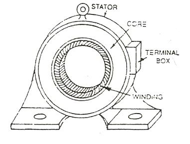
The stator is built up of high-grade alloy steel laminations to reduce eddy current losses. It has three main parts, namely the outer frame, the stator core, and a stator winding.
Outer frame
It is the outer body of the motor. Its main function is to support the stator core and to protect the inner parts of the machine. For small machines, the outer frame is casted, but for the large machine, it is fabricated. The figure below shows the stator construction.
 Stator Core
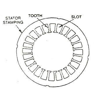
The stator core is built of high-grade silicon steel stampings. Its main function is to carry the alternating magnetic field which produces hysteresis and eddy current losses. The stampings are fixed to the stator frame. Each stamping is insulated from the other with a thin varnish layer. The thickness of the stamping usually varies from 0.3 to 0.5 mm. Slots are punched on the inner side of the stampings as shown in the figure below:
Stator windings
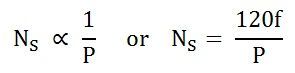
The core of the stator carries three-phase windings which are usually supplied from a three-phase supply system. The six terminals of the windings (two of each phase) are connected in the terminal box of the machine. The stator of the motor is wound for a definite number of poles, depending on the speed of the motor. If the number of poles is greater, the speed of the motor will be less and if the number of poles is less then the speed will be high.
As the relationship between the speed and the pole of the motor is given as:
The windings may be connected in star and delta.
Construction of Rotor
The rotor is also built of thin laminations of the same material as the stator. The laminated cylindrical core is mounted directly on the shaft. These laminations are slotted on the outer side to receive the conductors. There are two types of rotors.
Squirrel Cage Rotor
A squirrel cage rotor consists of a laminated cylindrical core. The circular slots at the outer periphery are semi-closed. Each slot contains an uninsulated bar conductor of aluminium or copper. At the end of the rotor the conductors are short-circuited by a heavy ring of copper or aluminium. The diagram of the cage rotor is shown below:
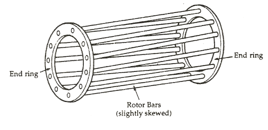
The rotor slots are usually not parallel to the shaft but are skewed. The skewing of the rotor conductors has the following advantages given below:
- It reduces humming and provides smooth and noise-free operation.
- It results in a uniform torque curve for different positions of the rotor.
- The locking tendency of the rotor is reduced. As the teeth of the rotor and the stator attract each other and lock.
- It increases the rotor resistance due to the increased length of the rotor bar conductors.
Advantages of Squirrel Cage Rotor
The following advantages of the cage rotor are given below:
- The cage rotor is cheaper, and the construction is robust.
- The absence of the brushes reduces the risk of sparking.
- Its maintenance is less.
- The power factor is higher.
- The efficiency of the cage rotor is higher.
Phase Wound Rotor
The phase wound rotor is also called a Slip Ring Rotor. It consists of a cylindrical core that is laminated. The outer periphery of the rotor has a semi-closed slot that carries 3 phase insulated windings. The rotor windings are connected to the star.
The slip ring induction motor is shown in the figure below:
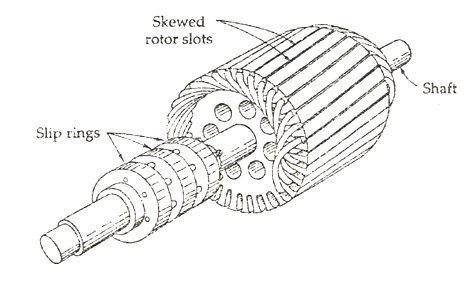
The slip rings are mounted on the shaft with brushes resting on them. The brushes are connected to the variable resistor. The function of the slip rings and the brushes is to provide a means of connecting external resistors in the rotor circuit. The resistor enables the variation of each rotor phase resistance to serve the following purposes given below:
- It increases the starting torque and decreases the starting current.
- It is used to control the speed of the motor.
In this type also, the rotor is skewed. A mild steel shaft is passed through the center of the rotor and is fixed to it. The purpose of the shaft is to transfer mechanical power.
Advantages of Phase Wound Rotor
Following are the advantages of the Phase Wound Rotor.
- High starting torque and low starting current.
- For controlling the speed of the motor, an external resistance can be added in the circuit.
Hence, in this way, an induction motor is constructed.
Thanks for the information you provide! keep the speed moving.
Excellent
Thanks for detailed information
Nice work..!
Tq a lot
It helped a lot! Thanks.
Thank u v much it helped a lot!!
Good and exact information… thank you
Thanks alot