The transformer mainly consists of the Magnetic circuit, electric circuit, dielectric circuit, tanks, and accessories. The main elements of the transformer are the primary and secondary windings and the steel core. The core of the transformer is made up of silicon steel in order to provide a continuous magnetic path. Usually, the core of the transformer is laminated for minimizing the eddy current loss.
Contents:
- Magnetic circuit
- Electric circuit
- Core Type Transformer
- Shell Type Transformer
- Dielectric Circuit
- Tanks and Accessories
Magnetic circuit
The magnetic circuit of a transformer consists of core and yoke. The circuit provides the path to the flow of magnetic flux. The transformer consists of a laminated steel core and the two coils. The two coils are insulated from each other and also from the core.
The core of the transformer is constructed from laminations of steel sheet or silicon steel assembled to provide a continuous magnetic path. At usual flux densities, the silicon steel material has low hysteresis losses.
The vertical position on which the coil is wound is called the limb while the horizontal position is known as the yoke.
Electric circuit
Construction of the electric circuit of the transformer consists of primary and secondary windings usually made of copper. The Conductors of the rectangular cross-section are generally used for low voltages winding and also for the high voltage winding for large transformers. Conductors of the circular cross-sectional area are used for high voltage winding in the small transformer.
According to the core construction and the manner in which the primary and secondary windings are placed around it, the transformer is named as core type and shell type.
Core Type Transformer
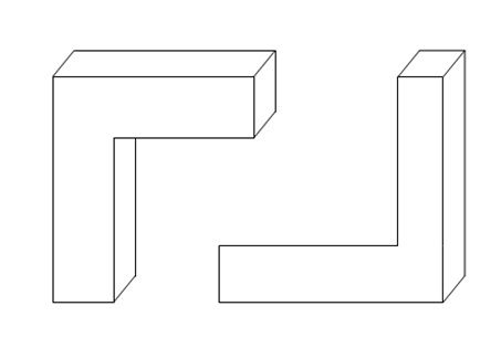
In a simple core type construction of the transformer, a rectangular frame laminations are formed to build the core of the transformer. The laminations are cut in the form of L-shape strips as shown in the figure below. In order to avoid high reluctance at the joints where laminations are butted against each other, the alternate layers are placed differently to eliminate the continuous joints.
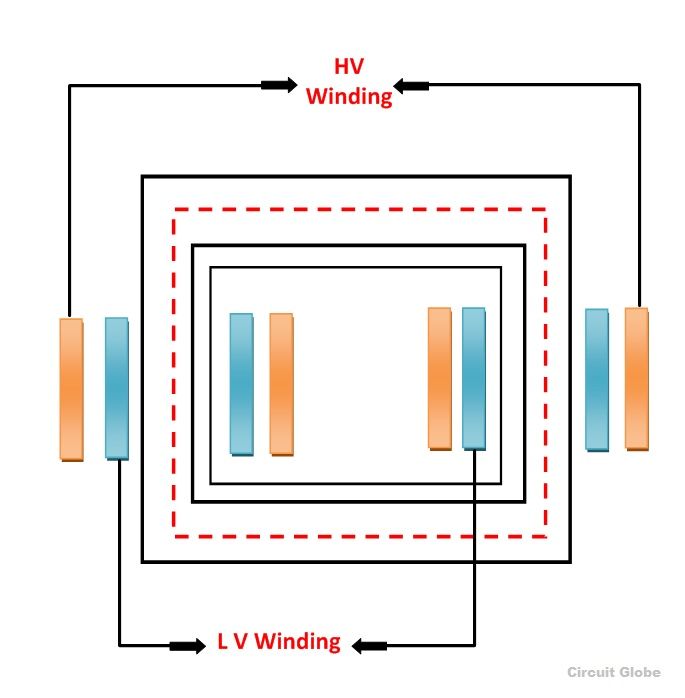
The primary and the secondary windings are interleaved to reduce the leakage flux. Half of each winding are placed side by side or concentrically on either limb of the core.
While placing these windings, insulation of Bakelite former is provided between the core and low voltage winding (LV), between the two windings that are between low voltage (LV) and high voltage (HV) windings and also in between coils and yoke. And also in between HV limb and yoke as shown in the figure below.
To reduce the insulation, the low voltage winding is always placed nearer to the core.
Shell Type Transformer
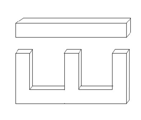
In a shell-type transformer, the individual laminations are cut in the form of long strips of E and I shape as shown in the figure below. It has two magnetic circuits, and the core has three limbs. The central limb carries the whole of the flux whereas the side limbs carry half of the flux. Therefore, the width of the center is double, to that of the outer limbs.
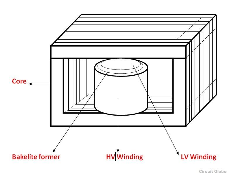
 The leakage flux is reduced by the subdivision of the windings which in return have lesser reactances. Both the primary and the secondary windings are placed on the central limb side by side. The low voltage winding is placed nearer to the core and the high voltage winding is placed outside the low voltage winding.
To reduce the cost of lamination between the core and the low voltage winding, the windings are formed and are wound to the cylindrical shape and then the core laminations are inserted later.
Dielectric Circuit
The dielectric circuit consists of insulations used in different places in the transformer to insulate the conducting parts. The core is laminated to minimize the eddy current losses. The laminations are insulated from each other by a light coating of varnish or by an oxide layer. The thickness of laminations varies from 0.35mm to 0.5mm for a frequency of 50 Hz.
Tanks and Accessories
Other different parts and accessories are also fitted on the transformer for its efficient work as well as for longer life and better services of the transformer. They are as follows:
Conservator
The Conservator is a cylindrical tank placed on the top or on the roof of the main tank of the transformer. A large cover is provided which can be opened from time to time for the proper maintenance and cleaning of the transformer. It acts as a reservoir for the transformer insulating oil.
When the transformer is fully loaded and the temperature of the transformer rises high, an increase in the volume of the air inside the transformer takes place. As the level of the oil increases and decreases simultaneously, thus, a conservatory provides adequate space for this expanded oil inside the transformer.
Breather
As in the human body, there is a heart, similarly, a breather acts as a heart for the transformer. When the temperature of the transformer rises, the insulating oil in the transformer gets heated up. This oil expands and contracts.
When the oil heats up and expands, the transformer breaths air in and thus the oil gets cooled and the level of oil goes down and the air is absorbed in it. This process of taking air in and out is called breathing of the transformer.
The level of oil in the chamber increases and decreases when the breather takes the air in and out for cooling of the oil. This air carries moisture, which contaminates the oil and thus the quality of oil gets deteriorate.
For eliminating this moisture content, the breather is filled with Silica Gel. The main function of the silica gel is to separate moisture from the oil, maintaining the quality of the insulating oil. Initially, the color of the silica gel is blue and as it absorbs the moisture from the oil it turns into pink color.
Fresh Silica gel drys down the air to a dew point below -40 degrees Celsius.
Explosion Vent
The explosion vent is a thin aluminum pipe placed at both the ends of the transformer to prevent the transformer from the damage. When the temperature increases in the transformer drastically and the excessive pressure is created inside the transformer, the explosive vent helps in releasing the pressure.
Radiator
The main function of the radiator is to cool the oil in the transformer. The radiator is the detachable device whose upper and lower portion is connected by a valve to the transformer tank. When the transformer cleaning and maintenance are done the valve prevents the draining of the oil when the radiator is detached from the transformer.
When the transformer is in the working conditions, the oil of the transformer gets heated and moves up in the main tank and enters the radiator through the upper valve. There it gets cooled and from the lower valve of the radiating unit the oil again enters the transformer tank and this process continues.
Bushings
The Bushings in the transformer are the insulting device that allows an electrical conductor to pass electrical energy safely through it. It provides electrical field strength to the insulation of the conductors to withstand if a large amount of electric energy passes through it. Solid porcelain type bushing is used in smaller transformer and oil-filled condenser type bushing is used in large transformer.
The most common cause of the failure of the bushing resulting in damage to the transformer is the entrance of the moisture. The power factor of the bushing will always be in stable condition, but if the variation is seen in the power factor that means there is deterioration in the insulation.
This can be identified by the tests known as acceptance or routine test and Doble Power Factor Test.