The effect of Armature (stator) flux on the flux produced by the rotor field poles is called Armature Reaction. When the current flows through the armature winding of the alternator, a flux is produced by the resulting MMF. This armature flux reacts with the main pole flux, causing the resultant flux to become either less than or more than the original main field flux.
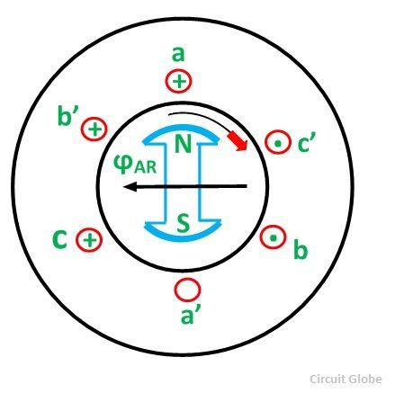
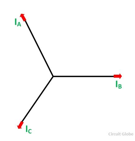
For simplicity, we consider a 3 phase, 2 pole alternator shown in the figure below:
The winding of each pole is assumed to be concentrated, but the effects of armature reaction will be the same as if a distributed winding were also used. The armature reaction in a synchronous machine affects the main field flux and varies differently for different power factors.
Here armature reaction is discussed for the following three conditions, namely unity power factor, zero power factor lagging, and zero power factor leading. The power factor can be defined as the cosine of the angle between the armature phase current and the induced EMF in the armature conductor in that phase.
Armature Reaction at Unity Power Factor
The direction of rotation of the rotor is considered clockwise. By applying the right-hand rule, the direction of the induced emf in various conductors can be found. The direction of rotation of the conductors is taken anticlockwise with respect to the rotor poles.
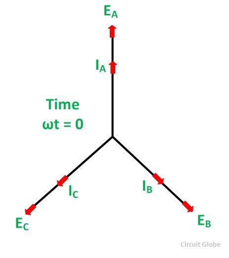
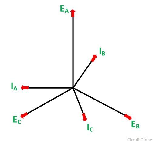
Suppose that the alternator is supplying current at unity power factor. The phase currents IA, IB, and IC will be in phase with their respective generated voltages, i.e., EA, EB, and EC as shown in the figure below:
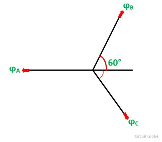
The positive direction of fluxes ϕA, ϕB, ϕC are shown in the figure below:
 The projection of a phasor on the vertical axis gives its instantaneous value.
At t=0, the instantaneous values of currents and fluxes are given by the equation shown below: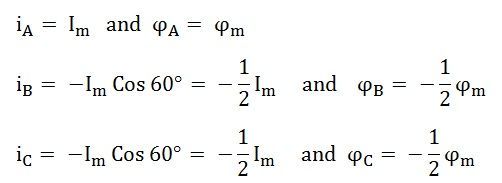
Where the subscript m denotes the maximum values of current and flux. Thus, the flux ϕA is along with OA, and the fluxes ϕB and ϕC are negative and acts opposite to each other represented by OB and OC respectively as shown in the figure below. The resultant of the fluxes can be found by resolving the fluxes horizontally and vertically.
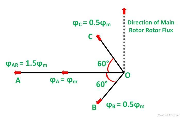 Resolving along the horizontal direction we get
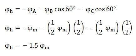
Similarly, resolving along the vertical direction we get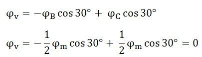
The resultant armature reaction flux is given by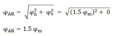
If the rotor is rotated, 30 degrees in a clockwise direction, the corresponding phasor diagram is shown below.
At the instant when ωt = 30⁰, the instantaneous values of currents and fluxes are given as: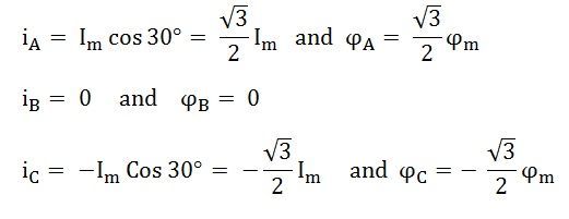
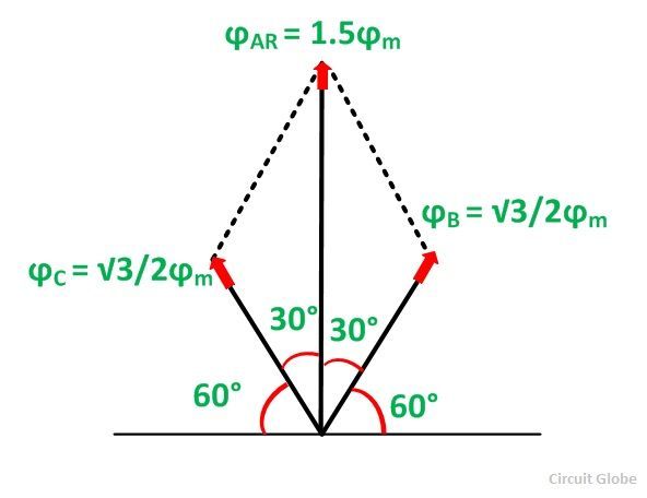
The space diagram for fluxes at ωt = 30⁰ is shown below:
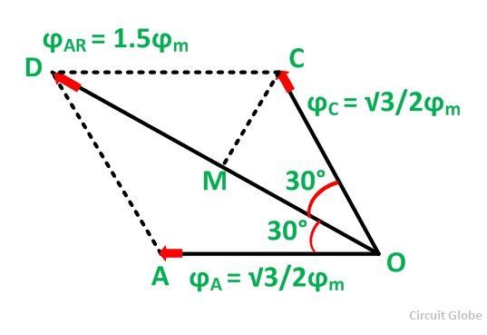
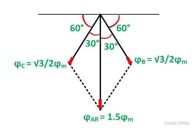
Here, ϕB = 0. The resultant armature reaction flux is given by the equation shown below: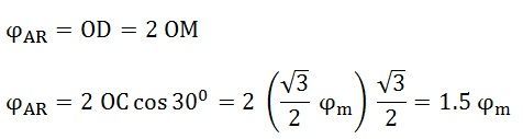
The direction of the resultant flux ϕAR is along OD, which makes an angle with the horizontal in the clockwise direction.
Hence, it is observed that the resultant flux ϕAR sets up by the current in the armature remains constant in magnitude equal to 1.5 ϕm and it rotates at synchronous speed. When the current is in phase with the induced voltage the armature reaction flux ϕAR lags behind the main field by 90⁰. This is called Cross Magnetizing Flux.
Armature Reaction at Lagging Power Factor
If the alternator is loaded with an inductive load of zero power factor lagging. The phase current IA, IB and IC will be lagging with their respective phase voltages EA, EB and EC by 90⁰. The figure below shows the phasor diagram of armature reaction at lagging load.

At time t = 0, the instantaneous values of currents and fluxes are given by: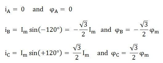
The space diagram of the magnetic fluxes is shown below:
The resultant flux ϕAR is given by the equation shown below: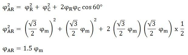
The direction of the armature reaction flux is opposite to the main field flux. Therefore, it will oppose and weaken the main field flux. It is said to be demagnetized.
Armature Reaction at Leading Power Factor
If the alternator is loaded with a load of zero power factor leading. The phase currents IA, IB, and IC will be leading their respective phase voltages EA, EB, and EC by 90⁰. The phasor diagram is shown below:
At time t = 0, the instantaneous values of currents and fluxes are given by the equations shown below: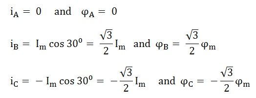
The direction of the flux is shown below in the phasor diagram.
The resultant flux is given by the equation shown below: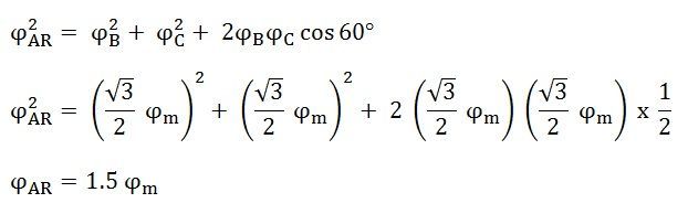 The direction of the armature reaction flux is in the direction of the main field flux. It is known as magnetizing flux.
Armature Reaction Nature
The following conclusion is given below:
- The armature reaction flux is constant in magnitude and rotates at synchronous speed.
- The armature reaction is cross-magnetizing when the generator supplies a load at unity power factor.
- When the generator supplies a load, at lagging power, the armature reaction is partly demagnetizing and partly cross-magnetizing.
This is all about Armature Reaction in a Synchronous Machine.
very well explained.
very well explained sir
Clear explanation
Thnxx mAm!
good explanation maam