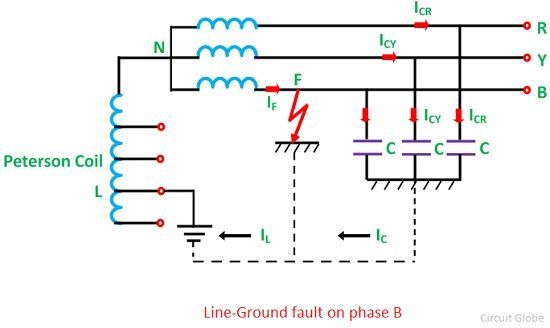
Peterson coil is an iron core reactor connected between transformer neutral and ground. It is used for limiting the capacitance earth fault current which is flowing when the line ground fault occurs in the line. The coil is provided with the tapping so that it can be adjusted with the capacitance of the system. The reactance is selected so that the current through the reactor is equal to the small line charging current which would flow into the line-to-ground fault.
Consider an LG fault in phase B at a point F as shown in the figure below. The line-to-ground voltage of phase B becomes zero. The voltage of the phases R and Y increase from phase values to line values.
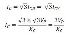
 The resultant of ICR and ICY is IC.
![]()
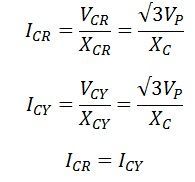 From the phasor diagram
 For balanced conditions
![]() If IC is equal to IL there will be no current through the ground, and there will be no tendency of the arcing grounds to occur. With the help of Peterson coil neutral grounding, arc resistance is reduced to such a small value that it is usually self-extinguishing. Therefore, Peterson coil is also known as a ground fault neutralizer or arc suppression coil.
If IC is equal to IL there will be no current through the ground, and there will be no tendency of the arcing grounds to occur. With the help of Peterson coil neutral grounding, arc resistance is reduced to such a small value that it is usually self-extinguishing. Therefore, Peterson coil is also known as a ground fault neutralizer or arc suppression coil.
Peterson coil is rated for a short time of about 5 minutes, or it is designed to carry its rated current continuously. It reduces the transient fault which occur due to lightning and also minimized the single line-to-ground voltage drops.
how to find rating of Peterson coil for neutral grounding of the system, if a 250 V, 50 HZ, 300 KM transmission line has a capacitance of earth of 0.03 micro farad per km per phase.