Definition: OTDR is an acronym used for Optical Time Domain Reflectometer. It is an instrument that is used to detect or analyze the scattered or back reflected light through an optical fiber due to impurities and imperfections in the fiber.
The operating principle of an OTDR is similar to that of radar. OTDR performs timed measurements of reflected light.
OTDR basically determines the characteristics of an optical fiber cable through which optical signal propagates.
It is also used to evaluate parameters such as splice losses, reflectance angle of a light signal, fiber attenuation etc.
When a signal is transmitted through an optical fiber cable then during transmission some part of the signal gets reflected. This reflection results in signal attenuation that mainly occurs due to defects in the fiber cable.
Thus, an OTDR is used as testing equipment in optical fiber communication system in order to determine the signal loss level inside a fiber cable.
Working of OTDR
An optical time domain reflectometer is test equipment used to evaluate the loss of signal inside an optical fiber by transmitting laser pulses inside the fiber and measures the scattered light signal.
The figure below represents the operational principle of an OTDR:
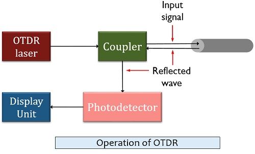
As we can see in the figure shown above that an optical time domain reflectometer contains a light source (mainly a laser) and a receiver along with a coupler or circulator. The coupler is connected with the fiber under test through a front panel connector.
The laser produces a short and intense light beam. These pulses are directed into the fiber link under test through a fiber optic coupler. A coupler splits the transmitted light pulse into two halves. Due to this, not all the transmitted pulse is directed inside fiber.
However, despite using a coupler if we use a circulator then this wastage of transmitted signal can be avoided. As circulators are highly directional devices that direct the overall light signal into the fiber as well as sends the reflected or scattered light signal into the detector.
By inserting circulators in the operational unit of OTDR, the dynamic range of the equipment can be improved. However, it also causes the overall cost of the system to increase considerably as circulator is highly expensive in comparison to couplers.
So, during the propagation of light pulses inside the fiber, due to absorption and Rayleigh scattering, some losses in the transmitted pulse occurs. Also, some losses are introduced due to splicers connected inside the fiber or the bends inside it.
Sometimes variation in the refractive index also causes the light energy to get reflected. This reflected energy reaches the OTDR and in this way, it detects the characteristics of the fiber link.
Specifications of OTDR
The specifications of OTDR are discussed below:
OTDR Trace
The reflected light is traced on the display screen of the reflectometer. The figure below represents the trace of the reflected power on the screen of OTDR:
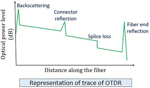
As we can see that in the above figure that the y-axis represents the optical power level of the reflected signal. While the x-axis represents the distance between the measurement points of the fiber link.
Now, on observing the trace of the OTDR, we can list the features of the reflected wave:
- The positive spikes in the trace are the result of Fresnel reflection at the joints of the fiber link and the imperfections in the fiber.
- The shifts in the curve are due to losses that occur due to fiber joints.
- A deteriorated tail in the curve is the outcome of Rayleigh scattering. As Rayleigh scattering is the result of fluctuations in the refractive index of the fiber and is the major reason for the attenuation of the signal inside the fiber.
OTDR Dead Zone
The dead zone of an OTDR is a crucial parameter. It is the distance in the fiber cable at which the defects cannot be measured properly.
Now the question arises why a dead zone occurs in an OTDR?
In case a very major portion of the transmitted signal is reflected then the received power at the photodetector is highly greater than the backscattered power level.
This saturates the OTDR with the light and hence it needs some duration to overcome the saturation. In this recovery duration, the reflectometer is unable to detect the backscattered reflection. Thereby leading to generate a dead zone in the trace of OTDR.
Performance parameter of OTDR
There exist two crucial parameters on which the performance of the OTDR depends. These are as follows:
Dynamic range: This is basically the difference between the backscattered optical power at the front connector and the peak of the noise level at the other end of the fiber. By evaluating the dynamic range one can get an idea about the maximal measured loss inside the fiber link and the time needed for such a measurement.
Measurement range: The measurement range is nothing but provides the distance up to which splice or connection points can be detected by the OTDR. Its value relies on the width of the transmitted pulse and the attenuation.
Hence, we can conclude that an OTDR is a very useful instrument used in an optical communication system. However, certain drawbacks are also associated like dead zone of OTDR.
Hello,
saw your very interesting work on OTDR and would be pleased receiving some more details of the circuit and especially the receiving photodetector and amplification chain.
Regards
Ralf Heil
what is the formula of to find the dynamic range in OTDR ?how it is related to laser pulse width?