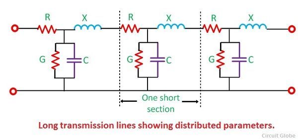
A transmission line having a length more than 240 km is consider as a long transmission line. In a long transmission line, parameters are uniformly distributed along the whole length of the line. For a long transmission line, it is considered that the line may be divided into various sections, and each section consists of an inductance, capacitance, resistance and conductance as shown below.
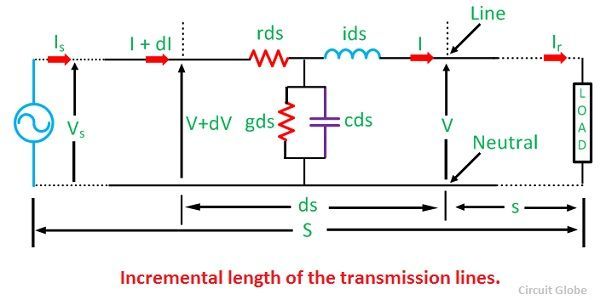
 Let’s consider a bit smaller part of a long transmission line having length ‘ds’ situated at a distance ‘s’ from the receiving end. Series impedance of the line is represented by ‘zds’ and ‘yds’ is the shunt impedance of the line. Due to charging current and corona loss the current is not uniform along the line. Voltage is also different in different parts of the line because of inductive reactance.
Where, r – resistance per unit length, per phase
l – inductance per unit length, per phase
c – capacitance per unit length, per phase
x – inductive reactance per unit length, per phase
z – series impedance per unit length, per phase
g – shunt leakage conductance, per phase to neutral per unit length
b – shunt leakage susceptance, per phase to neutral per unit length
y – shunt admittance per unit length, per phase to neutral.
For constant supply let,
V – voltage at a distance ‘s’ from the load end
V + dV – voltage at a distance (s+ds) from the load end
I – current at a distance ‘s’ from the load end
I + dI – current at a distance (s+ds) from the load end.
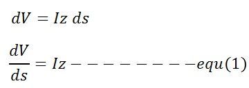
The difference in the voltage between the ends of the assumed sections of length ds is dV. This difference is caused by the series impedance of the line.
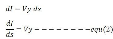
 Similarly, the difference between the two ends of the section resulting from the shunt admittance of the line is given by the equation
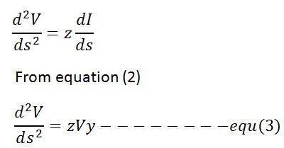
 for knowing the value of V, differentiate equation (1) with respect to ‘s’,
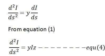
 and for current differentiate equation (2)
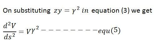
 equation (3) and (4) are similar in form and therefore their general equations are also similar.
 The equation (5) is the linear differential equation with constant coefficients.The general solution of this equations is
![]() Where, C1 and C2 are the arbitrary constants, and it is found from the known value of the V and I at some point of the line. For determining the value of I differentiate the above equation with respect to ‘s’
Where, C1 and C2 are the arbitrary constants, and it is found from the known value of the V and I at some point of the line. For determining the value of I differentiate the above equation with respect to ‘s’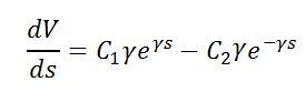 on combining the above equation with equation (1) we get,
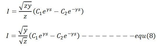
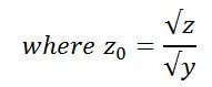
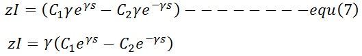 substituting the value of ϒ = √zy in equation (7) gives
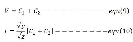
 The value of V and I at the receiving end where s = 0, is given by the equations
 The values of C1 and C2 are found from the simultaneous equations shown below
 and
and
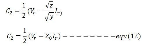
The value of C1 and C2 are substituted in general equations of voltage and current to obtain the steady-state values of V and I at any intermediate point distant ‘s’ from the receiving end.
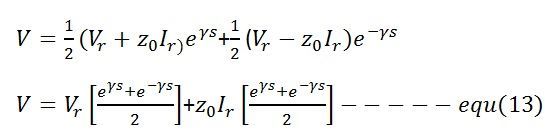 and
and
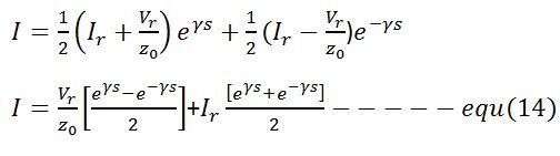 For governing the behaviour of transmission line in steady-state equation (13) and (14) are used. These equations can also be written in hyperbolic form by using hyperbolic constant shown below
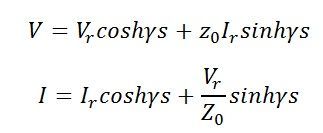
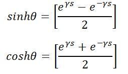 Substitutes the hyperbolic constant in equations (13) and (14) gives
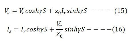
 these equations can also be written as sending end voltage and current equations by replacing s = S
 The ABCD parameters are defined below
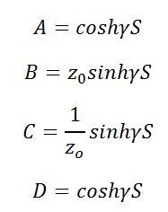 These equations help in evaluating the performance of the long line.