The circuit diagram of the three-phase induction motors is shown in the figure below. Magnetic contactor starter essentially consists of a set of start and stop push buttons with associated contacts, overload and underload protective devices.The start push button is a momentary contact switch that is held normally open by a spring. The stop push button is held normally closed by a spring.
Working of 3-Phase Induction Motor Protection System
When the start push button is pressed, the operating coil or the main contactor gets energised through the overload relay contacts OL. This closes the three main contacts M that connects the motor to the supply. At the same time, a set of auxiliary or maintaining contacts MC is closed.
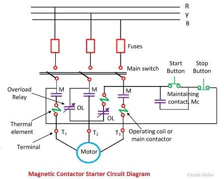
When the maintaining contacts MC are closed, a new circuit is established through stop push buttons, maintaining contacts MC and operating coil. Since the operating coil circuit is now maintained by the auxiliary contacts MC, the starter button is released. Now the motor starts.
For stopping a motor, the stop push buttons is pressed, the operation coil gets de-energized, thereby opening all the main contact and auxiliary contacts. If the supply fails or line voltage drops below a certain value, the maintaining contacts are opened. Upon return of the supply, the contactor cannot close until the start button is again pushed.
The contactor is controlled by a three-wire control circuit which maintains the interruption of the circuit even after the supply is restored. It is said to supply the under voltage protection for the motor. Such protection is provided when it is desired to prevent the unexpected starting of the motor.
Thermal overload relay is commonly used for motor overload protection. Both act to open the motor circuit and therefore to disconnect the motor from the source of supply. HRC fuses provide very rapid short circuit protection. Current is cut off by HRC fuse even before it attain prospective peak.
The selection of thermal relay is such that for the normal operating condition, the relay does not operate. A setting range is provided for adjustment for different in load conditions.