Hopkinson’s Test is also known as Regenerative Test, Back to Back and Heat Run Test. In Hopkinson Test, two identical shunt machines are required which are coupled both mechanically and electrically in parallel. One is acting as a motor and another one as a generator. The input to the motor is given by the supply mains.
Contents:
- Circuit Diagram of the Hopkinson’s Test
- Calculation of the Efficiency of the Machine by Hopkinson’s Test
- Advantages of Hopkinson’s Test
- Disadvantages of Hopkinson’s Test
The mechanical output of the motor drives the generator, and the electrical output of the generator is used in supplying the input to the motor. Thus, the output of each machine acts as an input to the other machine.
When both the machines are running on the full load, the supply input is equal to the total losses of the machines. Hence, the power input from the supply is very small.
The circuit diagram of the Hopkinson’s Test is shown in the figure below:
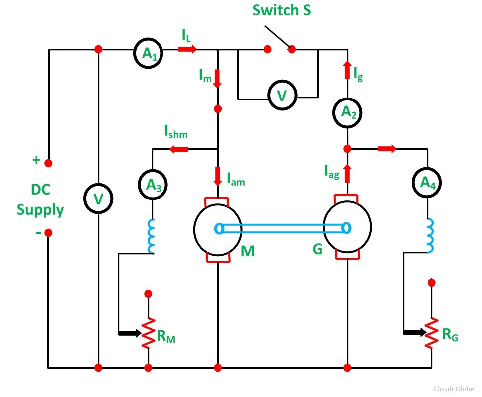 Supply is given and with the help of a starter, the machine M starts and work as a motor. The switch S is kept open. The field current of M is adjusted with the help of rheostat field RM, which enables the motor to run at rated speed. Machine G acts as a generator.
Since the generator is mechanically coupled to the motor, it runs at the rated speed of the motor.
The excitation of the generator G is so adjusted with the help of its field rheostat RG that the voltage across the armature of the generator is slightly higher than the supply voltage. In actual, the terminal voltage of the generator is kept 1 or 2 volts higher than the supply voltage.
When the voltage of the generator is equal and of the same polarity as that of the busbar supply voltage, the main switch S is closed, and the generator is connected to the busbars. Thus, both the machines are now in parallel across the supply.
Under this condition, when the machines are running parallel, the generator is said to float. This means that the generator is neither taking any current nor giving any current to the supply.
Now with the help of a field rheostat, any required load can be thrown on the machines by adjusting the excitation of the machines with the help of field rheostats.
Let,
- V be the supply voltage
- IL is the line current
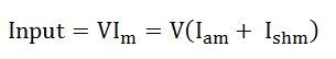
- Im is the input current to the motor
- Ig is the input current to the generator
- Iam is the motor armature current
- Ishm is the motor shunt field current
- Ishg is the generator shunt field current
- Ra is the armature resistance of each machine
- Rshm is the motor shunt field resistance
- Rshg is the generator shunt field resistance
- Eg is the generator induced voltage
- Em is the motor induced voltage or back emf
We know,
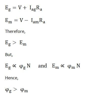
Since the field flux is directly proportional to the field current.
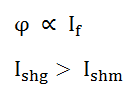
Thus, the excitation of the generator shall always be greater than that of the motor.
Calculation of the Efficiency of the Machine by Hopkinson’s Test
- Power input from the supply = VIL = total losses of both the machines
- Armature copper loss of the motor = I2am Ra
- Field copper loss of the motor = I2shm Rshm
- Armature copper loss of the generator = I2ag Ra
- Field copper loss of the generator = = I2shg Rshg
The constant losses Pc like iron, friction and windage losses are assumed to be equal and is written as given below.
Constant losses of both the machines = Power drawn from the supply – Armature and shunt copper losses of both the machines
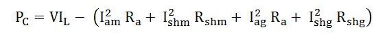 Assuming that the constant losses known as stray losses are divided equally between the two machines.
Total stray loss per machine = ½ PC
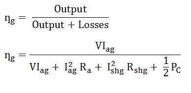
Efficiency of the Generator
- Output = VIag
- Constant losses for the generator is given as PC/2
- Armature copper loss = I2ag Ra
- Field copper loss = I2shg Rshg
The efficiency of the generator is given by the equation shown below:
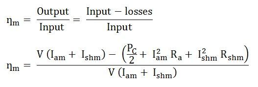
Efficiency of the Motor
- Constant losses of the motor are given as PC/2
- Armature copper loss = I2am Ra
- Field copper loss = I2shm Rshm
The Efficiency of the motor is given by the equation shown below:
Advantages of Hopkinson’s Test
The main advantages of using Hopkinson’s test are as follows:
- This method is very economical.
- The temperature rise and the commutation conditions can be checked under rated load conditions.
- Stray losses are considered, as both the machines are operated under rated load conditions.
- Large machines can be tested at rated load without consuming much power from the supply.
- Efficiency at different loads can be determined.
Disadvantage of Hopkinson’s Test
The main disadvantage of this method is the necessity of two practically identical machines for performing the Hopkinson’s test. Hence, this test is suitable for large DC machines.