Definition: The tachometer use for measuring the rotational speed or angular velocity of the machine which is coupled to it. It works on the principle of relative motion between the magnetic field and shaft of the coupled device. The relative motion induces the EMF in the coil which is placed between the constant magnetic field of the permanent magnet. The develops EMF is directly proportional to the speed of the shaft.
Mechanical and electrical are the two types of the tachometer. The mechanical tachometer measures the speed of shaft regarding revolution per minutes.
The electrical tachometer converts the angular velocity into an electrical voltage. The electrical tachometer has more advantages over the mechanical tachometer. Thus it is mostly used for measuring the rotational speed of the shaft. Depends on the natures of the induced voltage the electrical tachometer is categorized into two types.
- AC Tachometer Generator
- DC Tachometer Generator
DC Tachometer Generator
Permanent magnet, armature, commutator, brushes, variable resistor, and the moving coil voltmeter are the main parts of the DC tachometer generator. The machine whose speed is to be measured is coupled with the shaft of the DC tachometer generator.
The DC tachometer works on the principle that when the closed conductor moves in the magnetic field, EMF induces in the conductor. The magnitude of the induces emf depends on the flux link with the conductor and the speed of the shaft.
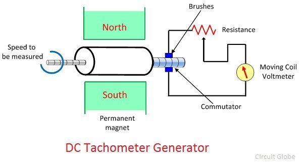 The armature of the DC generator revolves between the constant field of the permanent magnet. The rotation induces the emf in the coil. The magnitude of the induced emf is proportional to the shaft speed.
The commutator converts the alternating current of the armature coil to the direct current with the help of the brushes. The moving coil voltmeter measures the induced emf. The polarity of the induces voltage determines the direction of motion of the shaft. The resistance is connected in series with the voltmeter for controlling the heavy current of the armature.
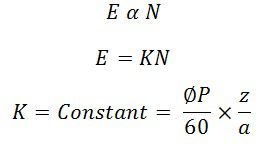
The emf induces in the dc tachometer generator is given as
 Where, E – generated voltage
Φ – flux per poles in Weber
P- number of poles
N – speed in revolution per minutes
Z – the number of the conductor in armature windings.
a – number of the parallel path in the armature windings.
 Advantages of the DC Generator
The following are the advantages of the DC Tachometer.
- The polarity of the induces voltages indicates the direction of rotation of the shaft.
- The conventional DC type voltmeter is used for measuring the induces voltage.
Disadvantages of DC Generator
- The commutator and brushes require the periodic maintenance.
- The output resistance of the DC tachometer is kept high as compared to the input resistance. If the large current is induced in the armature conductor, the constant field of the permanent magnet will be distorted.
AC Tachometer Generator
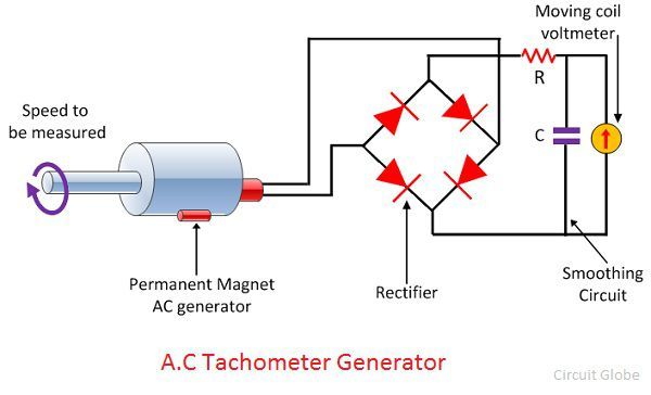
The DC tachometer generator uses the commutator and brushes which have many disadvantages. The AC tachometer generator designs for reducing the problems. The AC tachometer has stationary armature and rotating magnetic field. Thus, the commutator and brushes are absent in AC tachometer generator.
The rotating magnetic field induces the EMF in the stationary coil of the stator. The amplitude and frequency of the induced emf are equivalent to the speed of the shaft. Thus, either amplitude or frequency is used for measuring the angular velocity.
The below mention circuit is used for measuring the speed of the rotor by considering the amplitude of the induced voltage. The induces voltages are rectified and then passes to the capacitor filter for smoothening the ripples of rectified voltages.
 Drag Cup Rotor AC Generator
The drag cup type A.C tachometer is shown in the figure below.
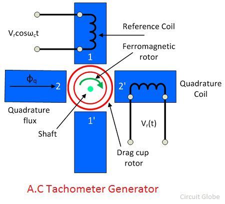 The stator of the generator consists two windings, i.e., the reference and quadrature winding. Both the windings are mounted 90° apart from each other. The rotor of the tachometer is made with thin aluminium cup, and it is placed between the field structure.
The rotor is made of the highly inductive material which has low inertia. The input is provided to the reference winding, and the output is obtained from the quadrature winding. The rotation of rotor between the magnetic field induces the voltage in the sensing winding. The induces voltage is proportional to the speed of the rotation.
Advantages
- The drag cup Tachogenerator generates the ripple free output voltage.
- The cost of the generator is also very less.
Disadvantage
The nonlinear relationship obtains between the output voltage and input speed when the rotor rotates at high speed.