The chopper converts the fixed DC voltage to variable DC voltage. Self-commutated devices (directly on or off devices via gate) like MOSFET, IGBT, power transistors, GTO and IGCT are used for making choppers because they can be commutated by low power control signal and do not need commutation circuit.
The chopper was operated at high frequency due to which it upgrade the motor performances by decreasing the ripple and removing the discontinuous conduction. The most important feature of chopper control is that the regenerative braking is carried out at very low generating speed when the drive is fed from a fixed voltage to low DC voltage.
Motoring Control
The transistor chopper controlled separately excited DC motor is shown in the figure below. The transistor Tr is operated periodically with period Tr and remains open for a duration Ton.The waveforms of motor terminal voltage and armature current are shown in the figure below. During on the motor terminal voltage is V and operation of the motor is described as
![]()
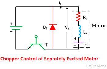 In this interval, the armature current raises from ia1 to ia2. This interval is called duty interval because the motor is directly connected to the source.
At t = ton, Tr is turned off. Motor current freewheels through diode Df and motor terminal voltage is zero during interval ton≤ t ≤ T. Motor operation during this interval is known as freewheeling interval and is described by
![]()
Motor current decreases from ia2 to ia1 during this interval.The ratio of duty interval ton to chopper period T is called duty cycle.
![]()
Regenerative Braking
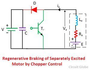
Chopper for regenerative braking operation is shown in the figure below. The transistor Tr is operated periodically with a period T and on-period of ton. The waveform of motor terminal voltage va and armature current ia for continuous conduction is shown in the figure below. The external inductance is added to increase the value of La. When the transistor is on, ia increased from ia1 to ia2.
 The mechanical energy is converted into electrical energy by the motor, now working as a generator, partly increased the stored magnetic energy in the armature circuit inductance and the remainder is dissipated in armature and transistors.

When the transistor is turned off, the armature current flows through diode D and the source V and reduces from ia2 to ia1. The stored electromagnetic energy and the energy supplied by the machine are fed to the source. The interval 0 ≤ t ≤ ton is called energy storage interval and the interval ton ≤ t ≤ T called the duty interval.
Forward Motoring and Braking Control
The forward motoring operation of the chopper is obtained by the transistor Tr1 with the diode D1.The transistor Tr2 and diode D2 provide the control for forward regenerative braking operation.
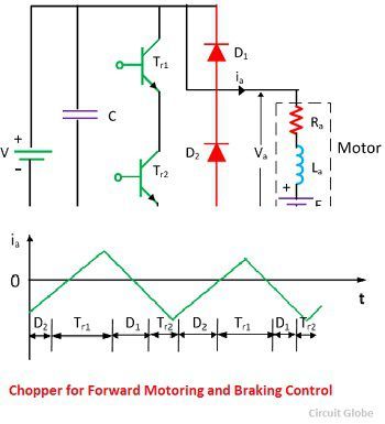
For the motoring operation, transistor Tr1 is controlled, and for braking operation, the transistor Tr2 is controlled. Shifting of control from Tr1 to Tr2 shift the operation from motoring to braking and vice versa.
Dynamic Control
The dynamic braking circuit and its waveform are shown in the figure below. During the interval between 0 ≤ t ≤Ton, ia increases from ia1 to ia2. The part of the energy is stored in inductance and rest is dissipated in Ra and TR.
 During the interval Ton≤ t ≤ T, ia decreases from ia2 to ia1.The energies generated and stored in inductances are dissipated in braking resistance RB, Ra and diode D.Transistor Tr control the magnitude of energy dissipated in RB and therefore control its effective value.