Characteristic is the graph between the two dependent quantities. It shows the steady-state characteristic of DC generators. The characteristic of the DC generators explains the relations between the loads, excitation and terminals voltage through the graph. Following are the three important characteristics of a DC Generator.
Magnetization Characteristic
This characteristic gives the variation of generating voltage or no-load voltage with field current at a constant speed. It is also called no-load or open circuit characteristic.
Internal Characteristic
Internal characteristic of DC Generator plots the curve between the generated voltage and load current.
External Characteristics (Load Characteristics)
External or load characteristics give the relation between the terminal voltage and load current at a constant speed.
Contents:
- Characteristic of Separately Excited DC Generator
- Voltage Buildup in Self Excited Generator or Shunt DC Generator
- Voltage- Current Characteristic of Compound DC Generator
Characteristic of Separately Excited DC Generator
In a separately excited DC Generator, a separate source of DC power is connected to the field winding. This source can be a battery, a diode rectifier, another DC Generator or a controlled rectifier. The circuit diagram of a separately excited DC Generator on loaded condition is shown below.
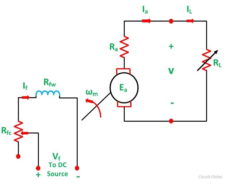
Let a generator be driven at a constant speed by a prime mover. The field excitation (If) is adjusted to give a rated voltage at no load. Throughout the operation, this value of voltage is kept constant.
Let,
- Rfw is the resistance of the field winding
- Rfc is the resistance of the field rheostat to control the field current.
- Ra is the total resistance of the armature circuit, including the brush contact resistance.
- RL is the load resistance.
- IL is the load current
- Ea is the internally generated voltage
- V is the terminal voltage
- Ia is the armature current
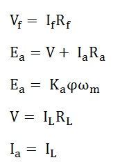
The various equations for a separately excited DC generator are as follows
If there were no armature reaction, the generated voltage V0 would be constant as shown by a straight line (red colour) in the figure below.
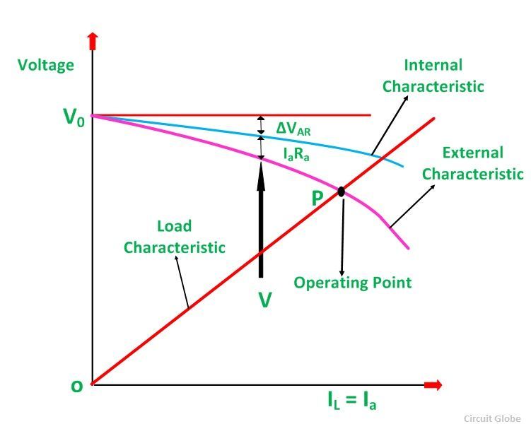
There is a voltage drop of Δ VAR because of the armature reaction. The internal characteristic (Ea ~ IL) is also shown in the above figure represented by a blue colour line. There is a voltage drop IaRa across the armature resistance Ra. The generator, external characteristic (V ~ IL) is also shown by the pink colour line.
The point P is called as Operating Point, which is the intersection between the generator, external characteristic and the load characteristic given by the relation V= ILRL. This point P gives the operating values of the terminal voltage and load current.
Voltage Buildup in Self Excited Generator or Shunt DC Generator
A self-excited generator is also known as DC Shunt Generator, as the field winding is connected in parallel with the armature. Thus, the armature voltage supplies the field current. This type of generator supplies its own field excitation.
The equivalent circuit of a shunt DC Generator is shown in the figure below:
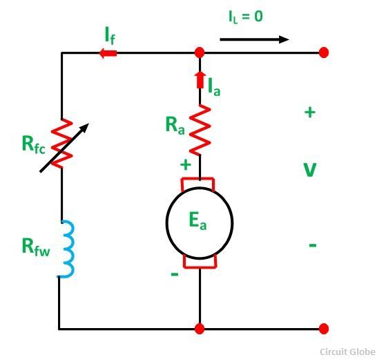
Considering the above figure let us assume that the generator is working at no-load condition, and the prime mover drives the armature at a certain speed. This generator will build up the desired terminal voltage. The residual flux present in the field poles of the DC generator is responsible for the voltage buildup. A small voltage Ear is generated and is given by the equation shown below.
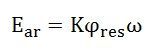
This voltage is of the order of 1 to 2 volts. This voltage causes a current If to flow in the field winding of the generator. The field current is given by the equation.

The flux is increased by a magnetomotive force produced by the field current. As a result, of this, the generated voltage Ea increases. This increased armature voltage increases the terminal voltage. With the increase in the terminal voltage, the field current If increases further. This, in turn, increases flux and hence the armature voltage is further increases, and the process of voltage buildup continues.
The voltage buildup curve of a DC shunt generator is shown below:
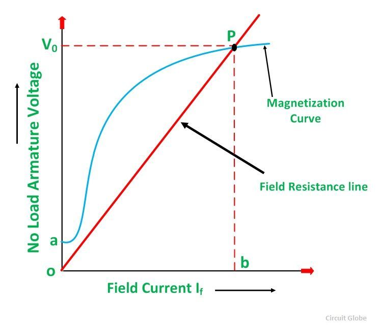
The generator is on no load during the process of voltage buildup, thus, the following equations shown below give the steady-state operation.

Since the field current If in a shunt generator is very small, the voltage drop If Ra can be neglected. Thus, equation (1) becomes:
![]()
The straight line given by V= IfRf shown in the above figure is known as Field Resistance Line.
The voltage buildup in the DC shunt generator for various circuit resistances is shown below:
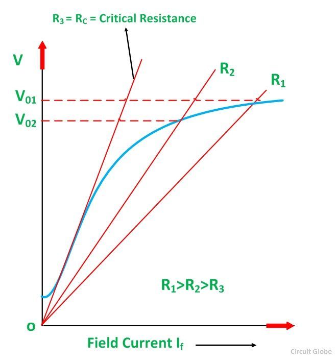
A decrease in the resistance of the field circuit reduces the slope of the field resistance line resulting in a higher voltage. An increase in the resistance of the field circuit increases the slope of the field resistance line, resulting in a lower voltage.
If the field circuit resistance is increased to Critical Resistance of the field (RC), the field resistance line becomes tangent to the initial part of the magnetization curve.
If the value of field resistance is higher than the critical resistance of the field value, the generator fails to excite. The curve shown below gives the variation of no-load voltage with the fixed field resistance and the variable speed of the armature.
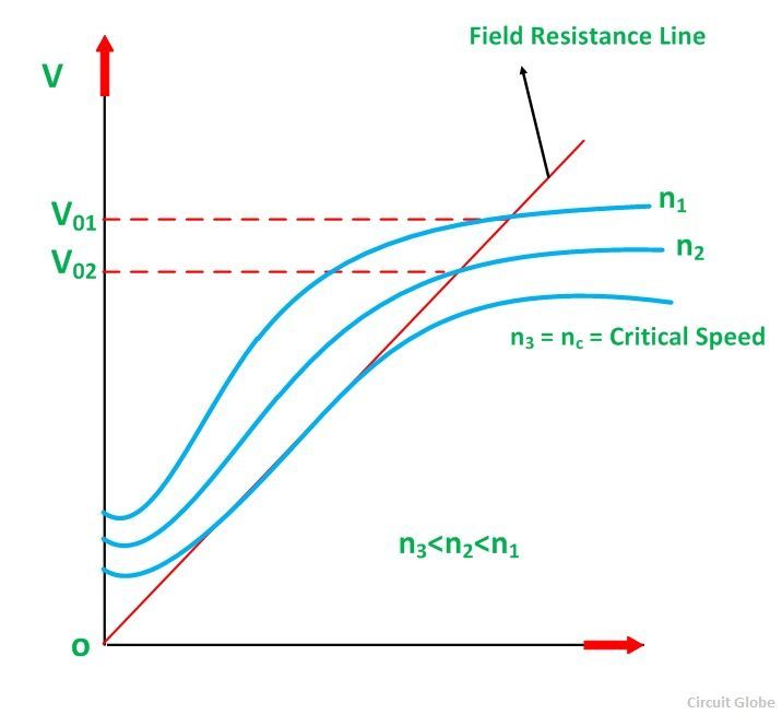
The magnetization curve varies with the speed and its ordinates for any field current is proportional to the speed of the generator. If the field resistance is kept constant and the speed id reduced, all the points on the magnetization curve are lowered.
At a particular speed, called the critical speed, the field resistance line becomes tangential to the magnetization curve. Below the critical speed, the voltage will not build up.
The following conditions must be satisfied for voltage buildup in a self-excited DC generator.
- There must be a sufficient residual flux in the field poles.
- The field terminals should be connected in such a way that the field current increases flux in the direction of residual flux.
- The field circuit resistance should be less than the critical field circuit resistance.
If there is no residual flux in the field poles, disconnect the field from the armature circuit and apply a DC voltage to the field winding.
This process is called Flashing the Field.
Voltage- Current Characteristic of Compound DC Generator
The voltage-current characteristic of compound generators are shown below:
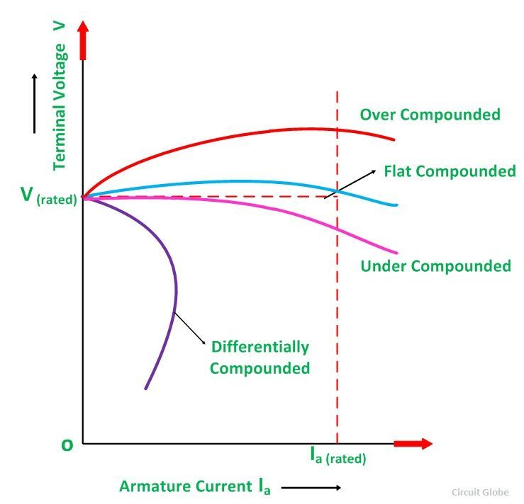
The Cumulatively Compound Generators can be Over Compounded, Flat Compounded and Under Compounded, depending upon the number of series field turns.
For over compounded generator, full load terminal voltage is higher than the no-load terminal voltage. In case of flat or level compounded generator, the terminal voltage at the full load is equal to the no-load terminal voltage. In an under compound generator the terminal voltage at the full load is less than the no-load terminal voltage.
In Differential Compounded Generators, the terminal voltage drops very quickly with the increasing armature current.
i got search box
Really simple and exceptionally well-written notes