Definition: The Synchro is a type of transducer which transforms the angular position of the shaft into an electric signal. It is used as an error detector and as a rotary position sensor. The error occurs in the system because of the misalignment of the shaft. The transmitter and the control transformer are the two main parts of the synchro.
Synchros System Types
The synchro system is of two types. They are
- Control Type Synchro.
- Torque Transmission Type Synchro.
Torque Transmission Type Synchros
This type of synchros has small output torque, and hence they are used for running the very light load like a pointer. The control type Synchro is used for driving the large loads.
Control Type Synchros System
The controls synchros is used for error detection in positional control systems. Their systems consist two units. They are
- Synchro Transmitter
- Synchro receiver
The synchro always works with these two parts. The detail explanation of synchros transmitter and receiver is given below.
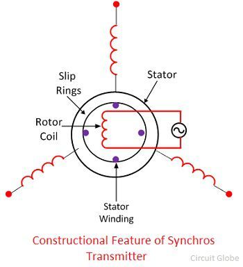
Synchros Transmitter – Their construction is similar to the three phase alternator. The stator of the synchros is made of steel for reducing the iron losses. The stator is slotted for housing the three phase windings. The axis of the stator winding is kept 120º apart from each other.
The AC voltage is applied to the rotor of the transmitter and it is expressed as
![]()
Where Vr – r.ms.value of rotor voltage
ωc – carrier frequency
The coils of the stator windings are connected in star. The rotor of the synchros is a dumbbell in shape, and a concentric coil is wound on it. The AC voltage is applied to the rotor with the help of slip rings. The constructional feature of the synchros is shown in the figure below.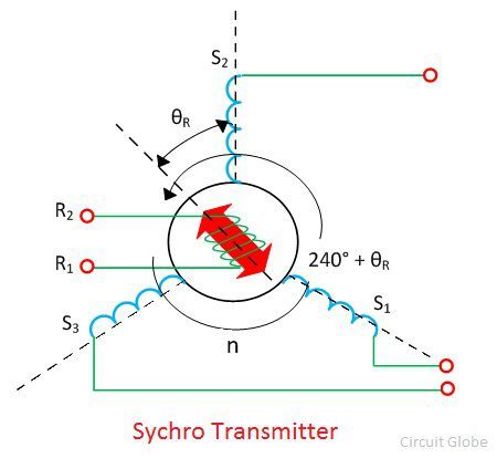
Consider the voltage is applied to the rotor of the transmitter as shown in the figure above. 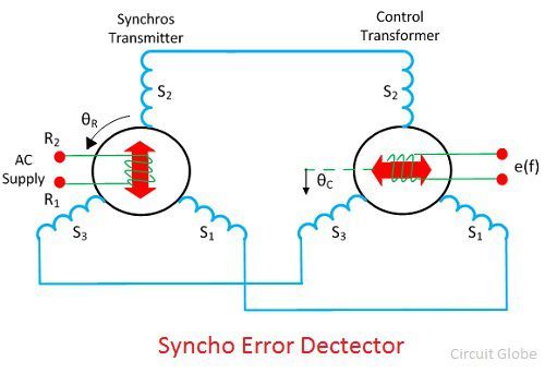
The voltage applied to the rotor induces the magnetizing current and an alternating flux along its axis. The voltage is induced in the stator winding because of the mutual induction between the rotor and stator flux. The flux linked in the stator winding is equal to the cosine of the angle between the rotor and stator. The voltage is induced in the stator winding.
Let Vs1, Vs2, Vs3 be the voltages generated in the stator windings S1, S2, and S3 respectively. The figure below shows the rotor position of the synchro transmitter. The rotor axis makes an angle θr concerning the stator windings S2.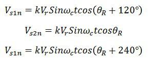
The three terminals of the stator windings are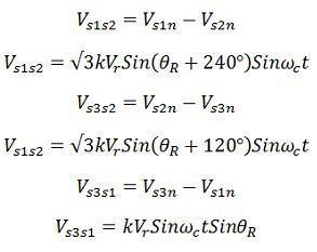
The variation in the stator terminal axis concerning the rotor is shown in the figure below.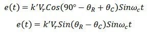
When the rotor angle becomes zero, the maximum current is produced in the stator windings S2. The zero position of the rotor is used as a reference for determining the rotor angular position.
The output of the transmitter is given to stator winding of the control transformer which is shown in the above figure.
The current of the same and magnitude flow through the transmitter and control transformer of the synchros. Because of the circulating current, the flux is established between the air gap flux of the control transformer.
The flux axis of the control transformer and the transmitter is aligned in the same position. The voltage generates by the rotor of control transformer is equal to the cosine of the angle between the rotors of the transmitter and the controller. The voltage is given as![]()
Where φ – angular displacement between the rotor axes of transmitter and controller.
Φ – 90º the axis between the rotor of transmitter and control transformer is perpendicular to each other. The above figure shows the zero position of the rotor of transmitter and receiver.
Consider the position of the rotor and the transmitter is changing in the same direction. An angle θR deflects the rotor of the transmitter and that of the control transformer is kept θC. The total angular separation between the rotors is Φ = (90º – θR + θC)
The rotor terminal voltage of the Synchro transformer is given as
The small angular displacement between their rotor position is given as
Sin (θR – θC) = (θR – θC)
On substituting the value of angular displacement in equation (1) we get
![]()
The synchro transmitter and the control transformer together used for detecting the error. The voltage equation shown above is equal to the shaft position of the rotors of control transformer and transmitter.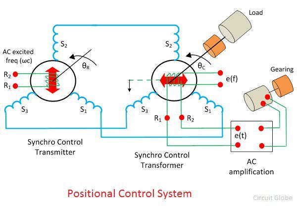
The error signal is applied to the differential amplifier which gives input to the servo motor. The gear of the servo motor rotates the rotor of the control transformer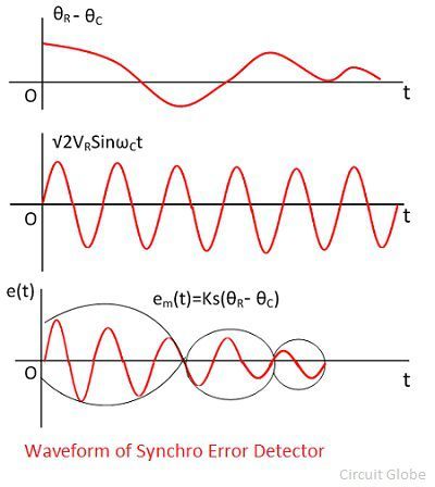
The figure above shows the output of the synchro error detector which is a modulated signal. The modulating wave above shown the misalignment between the rotor position and the carrier wave.![]()
Where Ks is the error detector.
Thank you for the explanation.