Definition: The full load test on a small transformer is very convenient, but on the large transformer, it is very difficult. The maximum temperature rise in a large transformer is determined by the full load test. This test is called, back-to-back test, regenerative test or Sumpner’s test.
The suitable load which absorbs the full load power of a large transformer will not easily be available. Hence a large amount of energy will be wasted. The back-to-back test determines the maximum temperature rise in a transformer, and hence the load is chosen according to the capability of the transformer.
Back to Back Test Circuit
The two identical transformer is used for the back to back test. Consider the Tr1 and Tr2 are the primary windings of the transformer connects parallel to each other. The nominal rated voltage and frequency is supplied to their primary winding. The voltmeter and ammeter are connected on their primary side for the measurement of the input voltage and current.
The secondary winding of the transformer is connected in series with the each other but with opposite polarity. The voltmeter V2 is connected to the terminal of the secondary winding for the measurement of the voltage.
The series opposition of the secondary winding is determined by connecting there any two terminal; the voltmeter is connected across their remaining terminals. If it is connected in series opposition, the voltmeter gives the zero reading. The open terminal is used for measuring the parameter of the transformer.
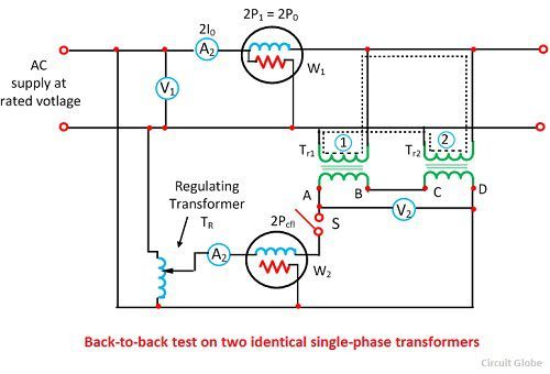
The above figure shows that the terminal B and C are connected to each other, and the voltage is measured across the terminal A and D.
Determination of Temperature Rise
The temperature rise of the transformer is determined by measuring the temperature of their oil after every particular interval of time. The transformer is operating back to back for the long time which increases their oil temperature. By measuring the temperature of their oil the withstand capacity of the transformer under high temperature is determined.
Determination of Iron Loss
The wattmeter W1 measures the power loss which is equal to the iron loss of the transformer. For determining the iron loss, the primary circuit of the transformer is kept closed. Because of the primary closed circuit, no current flows through the secondary windings of the transformer. The secondary winding behaves like an open circuit. The wattmeter is connected to their secondary terminal for the measurement of iron loss.
Determination of Copper Loss
The copper loss of the transformer is determined when the full load current flows through their primary and secondary windings. The additional regulating transformer is used for exciting the secondary windings. The full load current flows from the secondary to the primary winding. The wattmeter W2 measures the full load copper loss of the two transformers.