Definition: Single line diagram is the representation of a power system using the simple symbol for each component. The single line diagram of a power system is the network which shows the main connections and arrangement of the system components along with their data (such as output rating, voltage, resistance and reactance, etc.).
It is not necessary to show all the components of the system on a single line diagram, e.g., circuit breaker need not be shown in the load flow study but are the must for a protection study. In the single line diagram, the system component is usually drawn in the form of their symbols. Generator and transformer connections, star, delta and neutral earthing are indicated by symbols drawn by the side of the representation of these elements.
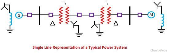
Circuit breakers are represented by rectangular blocks. The figure shown below represents the single line diagram of a typical block system. It is difficult to draw the line diagram of the few components. So for simplification, the impedance diagram is used for representing the power system components.
Impedance Diagram for the Power System
In impedance diagram, each component is represented by its equivalent circuit, e.g., the synchronous generator at the generating station by a voltage source in series with the resistance and reactance, the transformer by a nominal ∏-equivalent circuit. The load is assumed to be passive and are represented by a resistive and inductive reactance in the series. Neutral earthing impedance does not appear in the diagram as the balanced condition is assumed.
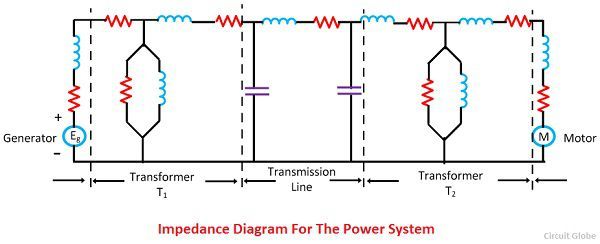
The diagram shown below is the balanced 3-phase diagram. It is also called positive sequence diagram. Three separate diagrams are also used for representing the positive, negative and zero sequence networks. The three separate impedance diagrams are used in the short circuit for the studies of unsymmetrical fault.
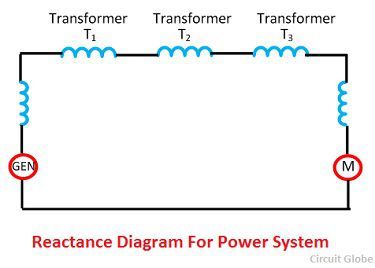
The impedance diagram can further be simplified by making certain assumptions and reduced to simplified reactance. Reactance diagram is drawn by neglecting the effective resistance of generator armature, transformer winding resistance, transmission line resistance line charging and the magnetising circuit of transformers. Reactance diagram of the power system is shown below.
Reactance Diagram for the Power System
The reactance diagram gives an accurate result for many power system studies, such as short-circuit studies, etc. The winding resistance, including the line resistance, are quite small in comparison with leakage reactance and shunt path which includes line charging and transformer magnetising circuit provide a very high parallel impedance with fault.
It is considered that if the resistance is less than one-third of the reactance, and resistance is ignored, then the error introduced will be not more than 5 %. If the resistance and reactance ignored errors up to 12% may be introduced. The errors mean their calculation gives a higher value than the actual value.
thank you