A transmission line having its length less than 80 km is considered as a short transmission line. In short transmission line capacitance is neglected because of small leakage current and other parameters (resistance and inductance) are lumped in the transmission line.
Single and three phase short transmission line
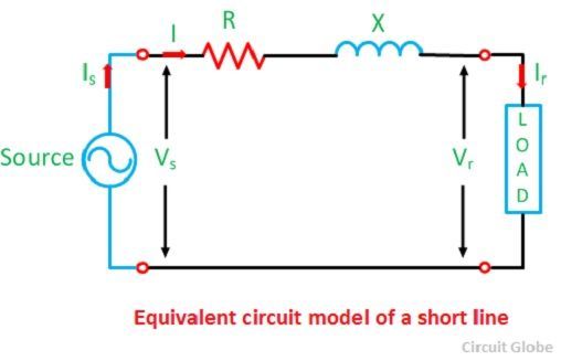
The single phase line is usually short in length and having low voltage. It has two conductors. Each conductor has resistance R and inductive reactance X. For convenience, it is considered that the parameters of the conductors are lumped into one conductor, and the return conductor is assumed to have no resistance and inductive reactance.

The single phase line and equivalent circuit model of the short transmission line are shown below in the figure. The resistance R and the inductive reactance X represent the loop resistance and the loop inductance of the short transmission line. Thus,
 R = loop resistance of the line = resistance of both outgoing and return conductors
= 2 × resistance of one conductor = 2R1
and X = loop reactance of the lines = reactance of both lead and return conductors
= 2 × inductive reactance to one conductor to neutral = 2X1
The end of the line where the load is connected is called receiving end. The end where the source of supply is connected is known as the sending end.
Let Vr = voltage at the receiving end
Vs= voltage at the sending end
Ir = current at the receiving end
Is = current at the sending end
cos∅r= power factor of the load
cos∅s = power factor at the sending end
The series impedance of the lines is given as,
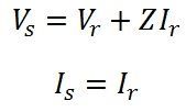
![]() In short transmission lines the shunt conductance and shunt capacitance of the line are neglected; hence, the current remains the same at all point of the line.
In short transmission lines the shunt conductance and shunt capacitance of the line are neglected; hence, the current remains the same at all point of the line.
Practically, we say that,
![]() The three phase line is made by using three single-phase conductors. Therefore, the calculation remains the same as explained for the single-phase line, the difference being that per phase basis is adopted. When working with balanced three phase line, it is assumed that all the given voltages are line-to-line values and all currents are line currents. Thus, for three phase line calculations,
The three phase line is made by using three single-phase conductors. Therefore, the calculation remains the same as explained for the single-phase line, the difference being that per phase basis is adopted. When working with balanced three phase line, it is assumed that all the given voltages are line-to-line values and all currents are line currents. Thus, for three phase line calculations,
power per phase = (1/3) × ( total power)
reactive volt-amperes per phase = ( 1/3) × (total reactive volt-amperes)
For a balanced 3-phase, star connected line,
phase voltage = 1/√3 × line voltage
Phasor Diagram
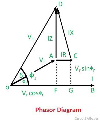
The phasor diagram for a load of lagging power factor is shown below.Let the receiving end voltage Vr be taken as reference phasor, and it is represented by OA in the phasor diagram. For lagging power factor, I lag behind Vr by an angle ∅r shown in the diagram, where OB = I.
The voltage drop in the resistance of the line = IR. Ir is represented by the phasor AC. It is in phase with the current and hence drawn parallel to OB. The voltage drop in the reactance of the line is IX and phasor CD represented it.
Reactance is lead by 90 degrees and therefore CD is drawn perpendicular to OB. Total impedance voltage drop IZ is the phasor sum of the resistive and reactive voltage drops, and AD gives it in the diagram.
OD is the sending end voltage Vs, and ∅s is the power factor angle between the sending end voltage and current. δ is the phase displacement angle between the voltages at the two ends.
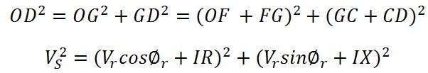
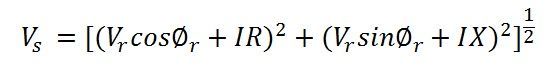
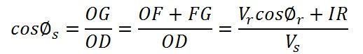
 The magnitude of Vs can be found from the right angle triangle OGD.
 Power factor of the load measured at the sending end is
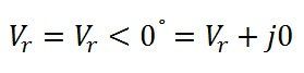
 If Vr be the reference phasor then,
 For lagging power factor cosΦr, I = I <−Φr = IcosΦr −jIsinΦr
For leading power factor cosΦr, I = I<+Φr = IcosΦr + jIsinΦr
For unity power factor, I = I<0° = I + j0°
The line impedance is given by
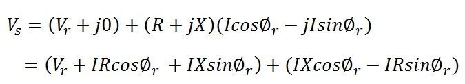
![]() Sending end voltage is
Sending end voltage is
![]() For lagging power factor,
For lagging power factor,
ABCD constants of a short line
General equation of the lines for representing voltage and current at the output terminal of the lines is shown below;
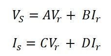
On comparing the output voltage and current of the short line with the above equations, the ABCD constant of the short line is given below.
 The ABCD constants for a short line are given by
Voltage regulation for short lines
It is the change in voltage at the receiving end when the full load at a given power factor is removed and the voltage at the sending end being constant. It can be written as;
At full load,
 At no load,
![]()
Therefore, voltage regulation is given as;
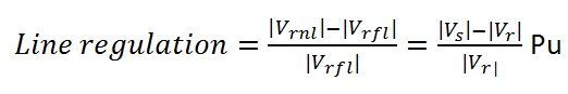 Voltage or line regulation depends on the power factor. If the line has leading power factor, then the receiving end voltage is greater and for lagging power factors sending end voltage is greater.
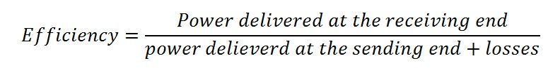
Line Efficiency
It is calculated by the formula given below
Thanks.
Best website for electrical subject. It is very useful for refering doubts and useful terms.
Very Helpful.
The voltage at the load is simply equal to the receiving end voltage?
It’s a lot of good jobs, plenty thanks.