A Printed Circuit Board or a Disc Armature motor consists of a rotor disc made of non-magnetic and non-conducting material. The armature winding and the commutator are printed with copper on both sides of the disc. The disc armature is placed between two sets of permanent magnets mounted on the ferromagnetic plates. Brushes are placed around the inner periphery.
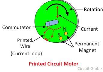
The arrangement of the assembly of the motor provides axial flux through the armature. The torque in the motor is produced by the interaction of the axial flux and the current flowing through the armature disc.
Advantages of Printed Circuit Board Motor
The various advantages of the PCB motor are as follows:
- The motor provides quick acceleration and retardation. As the inertia of the motor is very low and therefore, the ratio of torque and inertia is very high.
- The rotor does not contain iron, thus the armature inductance is low.
- The lower inductance of the motor reduces sparking and as a result life of brushes is increased.
- Cogging torque is absent because of the non-magnetic rotor.
- A PCB motor has a high overload current capacity.
- There is a negligible armature reaction and flux distortion and hence the speed torque curve of the motor is linear.
Applications of the Printed Circuit Board Motor
The characteristics of the PCB motor, i.e. the high torque and inertia ratio make the motor suitable for controlling applications. The various usage of the motor is as follows:
- It is used in high-speed tape readers.
- PCB motor is used in X-Y recorders, point to point tool positioners.
- Used in robots and other servo drives.
- It is also suitable for heavy-duty drives such as lawn mowers.
As there is an inbuilt optical position encoder thus it can be used in some place of the stepper motor.
can pcb motors used in inkjet printers or can inkjet printers designed around pcb motors
How to make simple PCB motor at home?