The measurement of earth resistance is made by the potential fall method. The resistance area of the earth electrode is the area of the soil around which a voltage gradient is measured with a commercial instrument. In the figure shown below E is the earth electrode under rest, and A is an auxiliary earth electrode positioned so that two resistance areas do not overlap. B is the second auxiliary electrode which is placed between E and A.
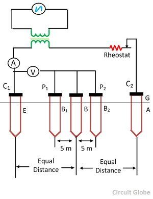
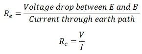
An alternating current of steady state value passes through the earth path from E to A and the voltage drop between E and B is measured.
The electrode B is moved from position B1 and B2 respectively so that the resistance area do not overlap. If the resistance values determined are of approximately the same in all three cases, the mean of the three readings can be taken as the earth resistance of the earth electrode.
The auxiliary earth electrode A must be driven in at a point further away from E and the above test repeated until the group of three readings obtained are in good agreement.The alternating current source is used to eliminate the electrolytic effect.
The test can be performed, with current at power frequency from a double wound transformer, using a voltmeter and an ammeter as shown in the figure above by mean of an earth tester.
The earth tester is a special type of Megger, which sends AC through earth and DC through the measuring instrument. It has got four terminals. Two terminals are shorted to form a common point which is connected to the earth electrode under test. The other two terminals are connected to the auxiliary electrode A and B respectively. The value of the earth resistance is indicated by the instrument directly when its handle is turned at a uniform speed.
the information is very good