The power which exists in the circuit when the voltage and current are out of phase to each other, such type of power is known as the reactive power. The formula measures the reactive power in the circuit![]()
The measurement of reactive power is essential because the value of reactive power shows the total power loss in the circuit. If the value of reactive power is low, the power factor of the load becomes poorer and more loss occurs in the system. The electrical system is classified by the number of phases used in the circuit, and according to these phases, the varmeter is categorised into two types.
- Single Phase Varrneter
- Polyphase Varmeter
Single Phase Varmeter
The reactive power of the single phase circuit is measured by the Varmeter (Volt ampere reactive meter). The varmeter is a type of the Electrodynamometer Wattmeter in which the pressure coil of the meter is made highly inductive. The terms “highly inductive” means, the voltage of the pressure coils lags at an angle of 90° with that of the current coil.
The current which passes through the current coil is the load current. The load current has a phase difference of 90° concerning that of the supply voltage, and it is given by the equation shown below.
![]()
The circuit diagram of the single phase varmeter is shown in the figure below.
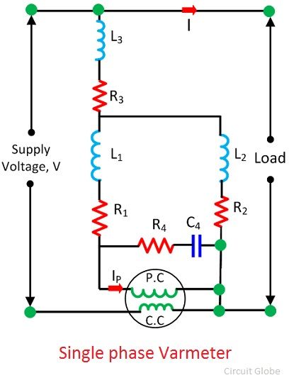
The Single Phase Varmeter gives the incorrect result because of the presence of harmonics. If the varmeter measures the reading at a different frequency from that which we used during the calibration then also the varmeter gives the inaccurate result.
Polyphase Varmeter
The reactive power exists in the circuit because of the phase displacement between the voltage and current. And this phase shifting is obtained from the phase shifting transformer. The phase shifting transformer consists two open circuit transformer which is connected in open delta configuration. The current coil is connected in series with the line. The pressure coil is connected to the common terminals of both the auto-transformer.
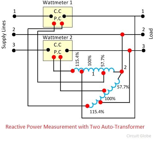
The 57.7%, 100%, and 115.4% shows the tapping of the auto-transformer. The auto-transformer shows the maximum line voltage of 115.4%. The pressure coil of one of the Wattmeter is connected to the 115.4% tapping of auto-transformer, while the other is connected to the 57.7%.
The voltage produces the pressure coil of wattmeter which is equal to the line voltage, but they have a phase shift of an angle of 90º. Similarly, the pressure coil of the Wattmeter 2 has the phase difference of 90º. The arithmetic readings of both the Wattmeters gives the total reactive power of the circuit.
Reactive Power Measurement in Balanced Three-Phase Circuit
The single wattmeter method is used for measuring the power of the balanced three-phase circuit. The current coil of the Wattmeter is connected to one phase, and the pressure coil is connected to the other phase of the line.
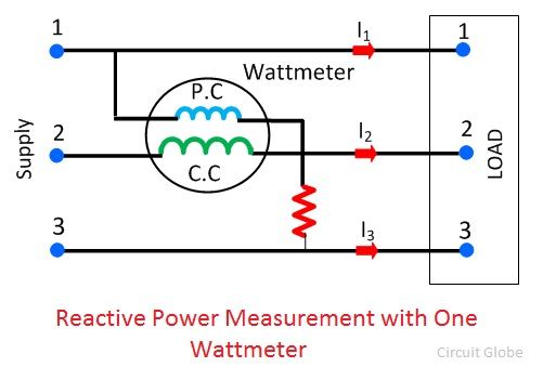
Let the current through the current coil – I2
Voltage across the pressure coil – V13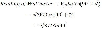
Total reactive volt amperes of the circuit
![]()
![]()
The phase angle