Definition: The Hay’s bridge is used for determining the self-inductance of the circuit. The bridge is the advanced form of Maxwell’s bridge. The Maxwell’s bridge is only appropriate for measuring the medium quality factor. Hence, for measuring the high-quality factor the Hays bridge is used in the circuit.
In Hay’s bridge, the capacitor is connected in series with the resistance, the voltage drop across the capacitance and resistance are varied. And in Maxwell bridge, the capacitance is connected in parallel with the resistance. Thus, the magnitude of a voltage pass through the resistance and capacitor is equal.
Construction of Hay’s Bridge
The unknown inductor L1 is placed in the arm ab along with the resistance R1. This unknown inductor is compared with the standard capacitor C4 connected across the arm cd. The resistance R4 is connected in series with the capacitor C4. The other two non-inductive resistor R2 and R3 are connected in the arm ad and bc respectively.
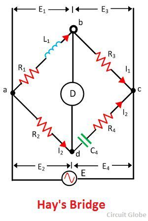
The C4 and R4 are adjusted for making the bridge in the balanced condition. When the bridge is in a balanced condition, no current flows through the detector which is connected to point b and c respectively. The potential drops across the arm ad and cd are equal and similarly, the potential across the arm ab and bc are equal.
Hay’s Bridge Theory
Let,
L1 – unknown inductance having a resistance R1
R2, R3, R4 – known non-inductive resistance.
C4 – standard capacitor
At balance condition, 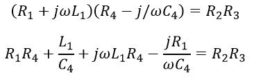
Separating the real and imaginary term, we obtain 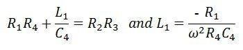
Solving the above equation, we have 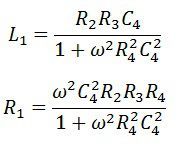
The quality factor of the coil is 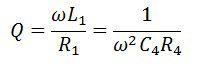
The equation of the unknown inductance and capacitance consists frequency term. Thus for finding the value of unknown inductance the frequency of the supply must be known.
For the high-quality factor, the frequency does not play an important role.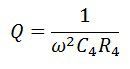
Substituting the value of Q in the equation of unknown inductance, we get 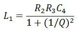
For greater value of Q the 1/Q is neglected and hence the equation become ![]()
Phasor Diagram of Hay’s Bridge
The phasor diagram of the Hay’s bridge is shown in the figure below. The magnitude and the phase of the E3 and E4 are equal and hence they are overlapping each other and draw on the horizontal axis. The current I1 flow through the purely resistive arm bd. The current I1 and the potential E3 = I3R3 are in the same phase and represented on the horizontal axis.
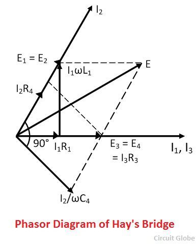
The current passes through the arm ab produces a potential drop I1R1 which is also in the same phase of I1. The total voltage drop across the arm ab is determined by adding the voltage I1R1 and ωI1L1.
The voltage drops across the arm ab and ad are equal. The voltage drop E1 and E2 are equal in magnitude and phase and hence overlap each other. The current I2 and E2 are in the same phase as shown in the figure above.
The current I2 flows through the arms cd and produces the I2R4 voltage drops across the resistance and I2/ωC4 voltage drops across the capacitor C4. The capacitance C4 lags by the currents 90º.
The voltage drops across the resistance C4 and R4 gives the total voltage drops across the arm cd. The sum of the voltage E1 and E3 or E2 and E4 gives the voltage drops E.
Advantages of Hay’s Bridge
The following are the advantages of Hay’s Bridge.
- The Hays bridges give a simple expression for the unknown inductances and are suitable for the coil having the quality factor greater than the 10 ohms.
- It gives a simple equation for quality factor.
- The Hay’s bridge uses small value resistance for determining the Q factor.
Disadvantages of Hay’s Bridge
The only disadvantage of this type of bridge is that it is not suitable for the measurement of the coil having the quality factor less than 10 ohms.
Note: The quality factor is a parameter which determines the relation between the stored energy and the energy dissipated in the circuit.
very nice
Very very nice
In the derivation, how is there a negative sign when separating imaginary terms?
thanks well explained
very very very nice
Why this bridge is suited for measurement of inductance of high Q coils