When a sinusoidal voltage is applied to the primary winding of a transformer, alternating flux ϕm sets up in the iron core of the transformer. This sinusoidal flux links with both primary and secondary winding. The function of flux is a sine function.
The rate of change of flux with respect to time is derived mathematically.
The derivation of the EMF Equation of the transformer is shown below. Let
- ϕm be the maximum value of flux in Weber
- f be the supply frequency in Hz
- N1 is the number of turns in the primary winding
- N2 is the number of turns in the secondary winding
Φ is the flux per turn in Weber
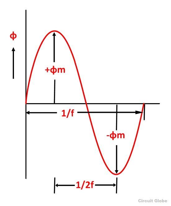 As shown in the above figure that the flux changes from + ϕm to – ϕm in half a cycle of 1/2f seconds.
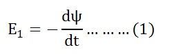
By Faraday’s Law
Let E1 be the emf induced in the primary winding
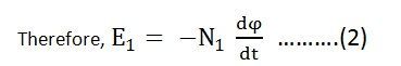
Where Ψ = N1ϕ
Since ϕ is due to AC supply ϕ = ϕm Sinwt
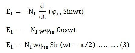
So the induced emf lags flux by 90 degrees.
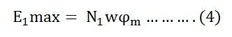
Maximum valve of emf
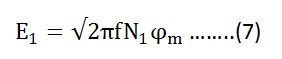
But w = 2πf
![]()
Root mean square RMS value is
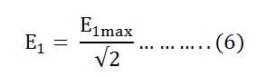
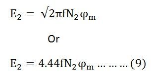
Putting the value of E1max in equation (6) we get
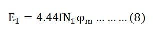
Putting the value of π = 3.14 in the equation (7) we will get the value of E1 as
Similarly
Now, equating the equation (8) and (9) we get
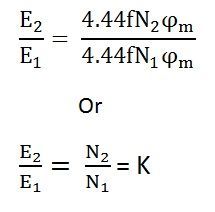
The above equation is called the turn ratio where K is known as the transformation ratio.
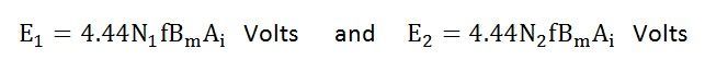
The equation (8) and (9) can also be written as shown below using the relation
(ϕm = Bm x Ai) where Ai is the iron area and Bm is the maximum value of flux density.
For a sinusoidal wave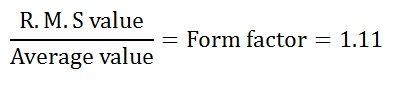
Here 1.11 is the form factor.
Thank you soo much it was too much help.
Thank you for goodness
it is helping me too much for study of electrical
thanks a lot …keep it up
You are welcome 😃
Nice and help full
Helped for my exams thanks
thankyou so much
This is very helpul. Thank you very much.
Neat and clean According topic, So much Helpful.,Thanks
Thanks it was very helpful
Thanks it is more helpful
Thanks sooo much
Thanks a lot
Nice solution given here.really its a very helpfull
Help me, I want to know 1.11 from where?
Will definitely help me in exam. Thanks a lot for these.
It is very beneficial for me..
Thank uh so muCh..for these😇
Thank you so much, helped me in a great deal.
Nice article
Recently came across this website..very neat and clear precise information..good for beginners…keep going 😊
ITs nice and helpful information
Dear mam excellent explanation. Thanks
this is a great work.
Thumbs up for u people helping me through my exams.
thanks
It is very important topic thank u so much
Well explained and informative
i really understood each step. thank you very much
All good
Thanks for sharing
It is very helpful to me and my friends
Thanks a lot
How to calculate number of turns in the primary coil of a transformer if the following is given:-
1. Voltage primary side
2. Core cross section area
3. Current in primary coil