Definition: The instrument whose working depends on the reaction between the magnetic field of moving and fixed coils is known as the Electrodynamo-meter Wattmeter. It uses for measuring the power of both the AC and DC circuits.
The working principle of the Electrodynamometer Wattmeter is very simple and easy. Their working depends on the theory that the current carrying conductor placed in a magnetic field experiences a mechanical force. This mechanical force deflects the pointer which is mounted on the calibrated scale.
Construction of Electrodynamometer Wattmeter
The following are the important parts of the Electrodynamometer Wattmeter.
- Fixed coil – The fixed coil connects in series with the load. It is considered as a current coil because the load current flows through it. For making the construction easy the fixed coil divide into two parts. And these two elements are parallel connected to each other. The fixed coil produces the uniform electric field which is essentials for the working of the instruments. The current coil of the instruments is designed to carry the current of approximately 20 amperes for saving the power.
- Moving Coil – The moving coil consider as the pressure coil of the instruments. It connects in parallel with the supply voltage. The current flows through them is directly proportional to the supply voltage. The pointer mounts on the moving coil. The movement of the pointer controls with the help of the spring. The current flows through the coil increases their temperature. The flows of currents control with the help of resistor which connects in series with the moving coil.
- Control – The control system provides the controlling torque to the instruments. The gravity control and the spring control are the two types of control system. Out of two, the Electrodynamometer Wattmeter uses spring control system. The spring control system is used for the movement of the pointer.
- Damping – The damping is the effect which reduces the movement of the pointer. In this Wattmeter the damping torque produces because of the air friction. The other types of damping are not used in the system because they destroy the useful magnetic flux.
- Scales and pointers – The instruments use a linear scale because their moving coil moves linearly. The apparatus uses the knife edge pointer for removing the parallax error which causes because of oversights.
Working of Electrodynamometer Wattmeter
The Electrodynamometer Wattmeter has two types of coils; fixed and the moving coil. The fixed coil connects in series with the circuit whose power consumption use to be measured. The supply voltage applies to the moving coil. The resistor controls the current across the moving coil, and it is connected in series with it.
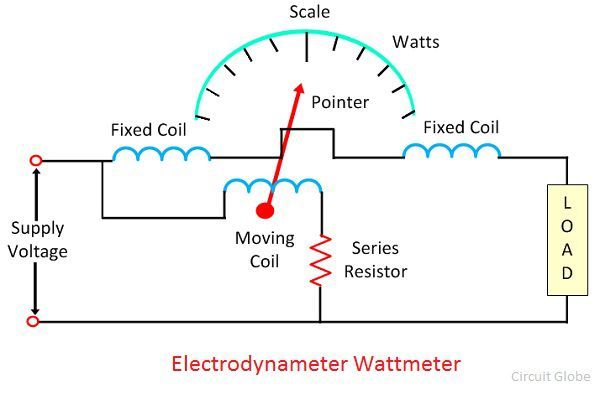
The pointer is fixed on the moving coil which is placed between the fixed coils. The current and voltage of the fixed and moving coil generate the two magnetic fields. And the interaction of these two magnetic fields deflects the pointer of the instrument. The deflection of the pointer is directly proportional to the power flows through it.
Theory of Electrodynamometer Wattmeter
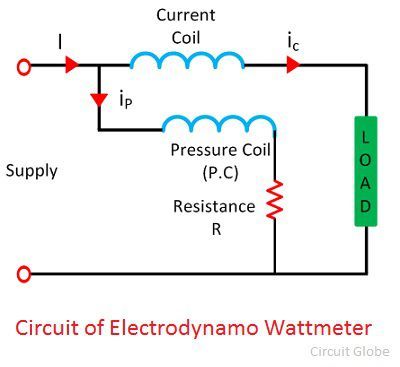
The circuit diagram of the electrodynamometer wattmeter is shown in the figure below.
The instantaneous torque acts on the pointer of the wattmeter and is given by the equation 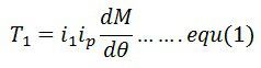
Where, ip – pressure coil current
ic– current coil current
dm/dθ – the rate of change of deflection of pointer concerning angle θ
The voltage across the pressure coil of the circuit is given as![]()
If the pressure coil is purely resistive, then their current is in phase with the voltage. And the value of current is given by the equation. 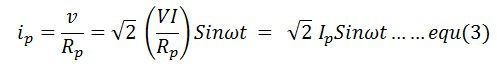
If the current coil lag by a voltage in phase angle Φ, the current through the current coil is given as
ip = √2Isin(ωt-∅)
The value of the current in the pressure coil is very small. Hence the current flows through the pressure coil is considered as the total load current. The torque acts on the coils becomes 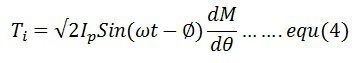
The average deflection torque is obtained by integrating the torque from 0 to T limit. The average deflection torque of the coil is given as 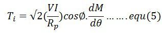
The controlling torque exerted on the spring is given by 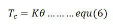
Errors in Electrodynamometer Wattmeter
The following are the errors in the Electrodynamometer Wattmeter
- Pressure Coil Inductance – The pressure coil of the Electrodynamometer has some inductance. Because of the inductance, the current of the pressure coils lags behind the voltage. Thus, the power factor of the wattmeter becomes lagging, and the meter reads high reading.
- Pressure Coil Capacitance – The pressure coil has capacitances along with the inductance. This capacitance increases the power factor of the instrument. Hence causes the error in the reading.
- Error due to Mutual Inductance Effect – The mutual inductance between the pressure and current coil produces an error.
- Eddy Current Error – The eddy current induces in the coil creates its own magnetic field. This field affects the main current flows through the coil. Thus, the error occurs in the reading.
- Stray Magnetic Field – The stray magnetic field disturbs the main magnetic field of the Electrodynamic Wattmeter. Thus, affect their reading.
- Temperature Error – The variation in temperature will change the resistance of the pressure coil. The movement of the spring, which provides the controlling torque also affected because of the temperature change. Thereby, the error occurs in the reading.
The calibration of the electrodynamometer wattmeter is same both for the AC and DC measurement.
Your article of any topic are written in very simple or optimised language that’s why everyone can understand the concept .
Really very helpful .
Please keep doing this.
Really very helpful your explanation in very simple language about electrodynamometer wattmeter
Material is simple,straight-forward and easy to understand.
Easy language, thanks