Definition: The armature reaction simply shows the effect of armature field on the main field. In other words, the armature reaction represents the impact of the armature flux on the main field flux. The armature field is produced by the armature conductors when current flows through them. And the main field is produced by the magnetic poles.
The armature flux causes two effects on the main field flux.
- The armature reaction distorted the main field flux.
- It reduces the magnitude of the main field flux.
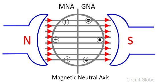
Consider the figure below shows the two poles dc generator. When no load connected to the generator, the armature current becomes zero. In this condition, only the MMF of the main poles exists in the generator. The MMF flux is uniformly distributed along the magnetic axis. The magnetic axis means the centre line between the north and south pole. The arrow in the below-given image shows the direction of the magnetic flux ΦM. The magnetic neutral axis or plane is perpendicular to the axis of the magnetic flux.
The MNA coincides with the geometrical neutral axis (GNA). The brushes of the DC machines are always placed in this axis, and hence this axis is called the axis of commutation.
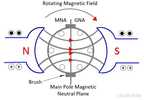
Consider the condition in which only the armature conductors carrying current and no current flows through their main poles. The direction of the current remains the same in all the conductors lying under one pole. The direction of current induces in the conductor is given by the Fleming right-hand rule. And the direction of flux generates in the conductors is given by the corkscrew rule.
The direction of current on the left sides of the armature conductor goes into the paper (represented by the cross inside the circle). The armature conductors combine their MMF for generating the fluxes through the armature in the downward direction.
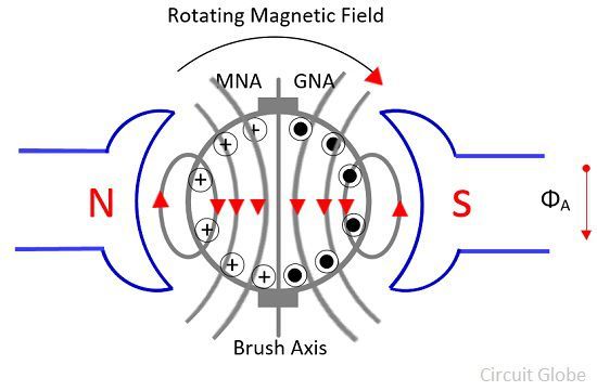
Similarly, the right-hand side conductors carry current, and their direction goes out of the paper (shown by dots inside the circle). The conductor on the right-hand sides is also combining their MMF for producing the flux in the downwards direction. Hence, the conductor on both sides combines their MMF in such a way so that their flux goes downward direction. The flux induces in the armature conductor ΦA is given by the arrow shown above.
The figure below shows the condition in which the field current and the armature current are simultaneously acting on the conductor.
This happens when machines running at no-load condition. Now the machine has two fluxes, i.e., the armature flux and the field pole flux. The armature flux is produced by the current induced in the armature conductors while the field pole flux is induced because of the main field poles. These two flux combines and gives the resultant flux ΦR as shown in the figure above.
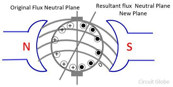
When the field flux enters into the armature, they may get distorted. The distortion increases the density of the flux in the upper pole tip of the N-pole and the lower pole tip of the south pole. Similarly, the density of flux decreases in the lower pole tip of the north pole and the upper pole tip of the south pole.
The resultant flux induces in the generator are shifted towards the direction of the rotation of the generator. The magnetic neutral axis of poles is always perpendicular to the axis of the resultant flux. The MNA is continuously shifted with the resultant flux.
Effect of Armature Reaction
The effects of Armature Reaction are as follows:-
- Because of the armature reaction the flux density of over one-half of the pole increases and over the other half decreases. The total flux produces by each pole is slightly less due to which the magnitude of the terminal voltage reduces. The effect due to which the armature reaction reduces the total flux is known as the demagnetizing effect.
- The resultant flux is distorted. The direction of the magnetic neutral axis is shifted with the direction of resultant flux in the case of the generator, and it is opposite to the direction of the resultant flux in the case of the motor.
- The armature reaction induces flux in the neutral zone, and this flux generates the voltage that causes the commutation problem.
The MNA axis is the axis in which the value of induced MEF becomes zero. And the GNA divides the armature core into two equal parts.
Awesome explanation…..it helped me a lot….thank you
Superb
Thanks 😊😊😊😊😊☺
very easy language
Nice mam.. It’s really helped me out ☺️
Really very much helpful.Thank you 🥰
Wonderful super
I really appreciate it
I saw the video of this lecture on Youtube and I really got the concept of armature reaction, it gonna help me in my exam
thanks for your information and keep it up making more videos and uploading lectures (GOD bless you) .
Best reference site helped me thank you