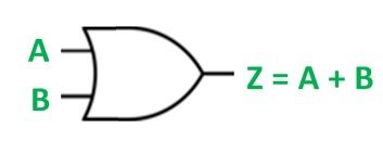
An OR gate has two or more than two inputs and one output signal. It is called an OR gate because the output signal will be high only if any or all input signals are high.
The OR gate follows the logical operation of the input and output signals. It permits the signal to pass and stop through it. The logic symbol for the gate is shown below:
 The switching circuit of the gate operation is shown below:
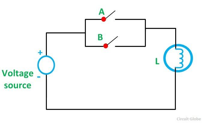 A lamp L is connected to a voltage source. A and B are the two switches. The switching circuit illustrates that the lamp L will glow when either of the switches A or B or both A and B is closed. The lamp will go off when both the switches are in the open condition.
The truth table of the gate is given below:
| A | B | Z |
|---|---|---|
| 0 | 0 | 0 |
| 0 | 1 | 1 |
| 1 | 0 | 1 |
| 1 | 1 | 1 |
From the truth table, it is clear that, when the inputs of the OR gate are LOW that is 0, the output will be 0. If any one of the inputs or both the inputs of the OR gate is 1 that is HIGH, the output will be high, i.e., 1.