Definition: The meter which measures the resistance and the continuity of the electrical circuit and their components such type of meter is known as the ohmmeter. It measures the resistance in ohms. The micro-ohmmeter is used for measuring the low resistance and the mega ohmmeter measures the high resistance of the circuit. The ohmmeter is very convenient to use but less accurate.
Types of Ohmmeter
The ohmmeter gives the approximate value of resistance. It is very portable and hence used in the laboratory. It is of three types; they are the series ohmmeter, shunt ohmmeter and multi-range ohmmeter. The detail explanation of their types is given below.
Series Ohmmeter
In series ohmmeter, the measuring resistance component or circuit is connected in series with the meter. The value of resistance is measured through the d’Arsonval movement connected in parallel with the shunt resistor R2. The parallel resistance R2 is connected in series with the resistance R1 and the battery. The component whose resistance is used to be measured is connected in series with the terminal A and B.
The circuit diagram of the series ohmmeter is shown in the figure below.
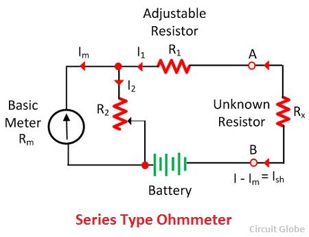
When the value of unknown resistance is zero the large current flow through the meter. In this condition, the shunt resistance is adjusted until the meter indicates the full load current. For full load current, the pointer deflects towards zero 0 ohms.
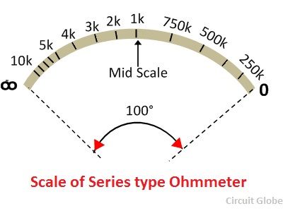
When the unknown resistance Rx is removed from the circuit the resistance of the circuit becomes infinite and no current flow through the circuit. The pointer of the meter deflects towards the ∞ (infinity). The meter shows the infinite resistance at zero current and the zero resistance when full range current flows through it.
When the unknown resistance is connected in series with the circuit and if their resistance is high, then the pointer of the meter deflects toward the left. And if the resistance is low, then pointer deflects toward the right.
Shunt Type Ohmmeter
The meter in which the measuring resistance is connected in parallel with the battery is known as the shunt ohmmeter. It is mainly used for measuring the low-value resistance.
The circuit diagram of the shunt ohmmeter is shown in the figure below.
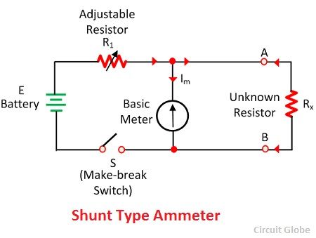
The battery (E), basic meter (Rm) and the adjustable resistance are the main components of the shunt ohmmeter. The unknown resistance is connected across terminal A and B.
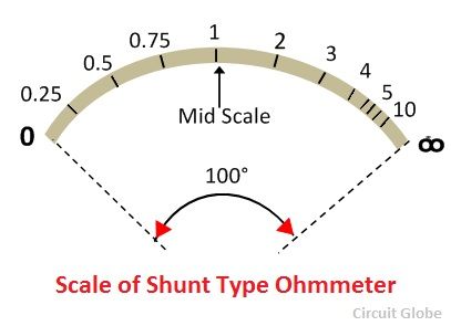
When the value of unknown resistance is zero the meter current becomes zero. And if the resistance becomes infinite (i.e., the terminal A and B are open) then the current passes through the battery and the pointer shows the full-scale deflection toward left. The shunt type ohmmeter has the zero mark (no current) on the left of the scale and the infinity mark on their right side.
Multi-Range Ohmmeter
The range of this type of ohmmeter is very high. The meter has adjuster which selects the range according to need.
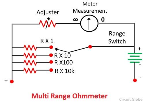
For example, consider we use the meter for measuring the resistance under 10 ohms. For this first, we have to set the range of 10 ohms. The resistance whose value is used to be measured is connected in parallel with the meter. The magnitude of the resistance is determined through the deflection of the pointer.