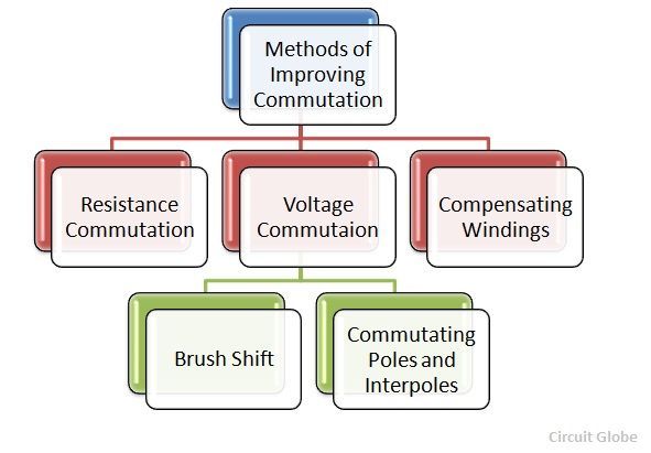
There are three main methods of Improving commutation or obtaining sparkles Commutation. These are Resistance Commutation and Voltage Commutation and Compensating Winding.
Further, the voltage commutation consists of another two methods which are used to produce the injected voltage, named as commutating poles or interpoles and Brush Shift.
 The following methods of Improving Commutation are explained below in detail.
Contents:
- Resistance Commutation
- Voltage Commutation
- Brush Shift
- Commutating Poles or Interpoles
- Compensating Windings
Resistance Commutation
The Resistance Commutation method uses carbon brushes for improving commutation. The use of carbon brushes makes contact resistance between commutator segments and brushes high. This high contact resistance has the tendency to force the current in the short-circuited coil to change according to the commutation requirements.
Voltage Commutation
In the Voltage Commutation method, the arrangement is made to induce a voltage in the coil undergoing the commutation process, which will neutralize the reactance voltage. This injected voltage is in opposition to the reactance voltage. If the value of the injected voltage is made equal to the reactance voltage, there will be a quick reversal of current in the short-circuited coil and as a result, there will be sparkles commutation.
The two methods used to produce the injected voltage in opposition to the reactance voltage are as follows.
Brush Shift
The effect of armature reaction is to shift the magnetic neutral axis (MNA) in the direction of rotation for the generator and against the direction of rotation for the motor. Armature reaction establishes a flux in the neutral zone. A small voltage is induced in the commutating coil since it is cutting the flux.
Commutating Poles or Interpoles
Interpoles are narrow poles placed in between the main poles and are attached to the stator Interpoles are also called commutating poles or Campoles. The interpoles windings are connected in series with the armature because the interpoles must produce fluxes that are directly proportional to the armature current.
The armature and the interpoles mmfs are affected simultaneously by the same armature current. Consequently, the armature flux in the commutating zone, which tends to shift the magnetic neutral axis, is neutralized by an appropriate component of interpole flux.
The interpoles must induce a voltage in the conductors undergoing commutation that is opposite to the voltage caused by the neutral plane shift and reactance voltage.
In case of a generator:
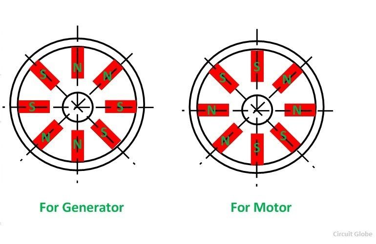
The neutral plane shifts are in the direction of rotation. Thus, the conductor undergoing the commutation, the polarity of the interpole must be the same i.e. similar to the next main pole in the direction of rotation. To oppose this voltage, the interpoles must have the opposite flux, which is the flux of the main pole ahead according to the direction of rotation.
In case of a motor:
For a motor, the neutral plane shifts opposite to the direction of rotation, and the conductors undergoing commutation have the same flux as the main pole. For opposing this voltage, the interpole must have the same polarity as the previous main pole. The polarity of an interpole and main pole is opposite in the direction of rotation.
The polarity of interpoles is shown in the figure below:
 The Interpoles serve only to provide sufficient flux to assure good commutation. They do not overcome the distortion of the flux resulting from cross-magnetizing mmf of the armature.
During severe overloads or rapidly changing loads, the voltage between adjacent commutator segments may become very high. This ionizes the air around the commutator to the extent that it becomes sufficiently conductive. An arc is established from brush to brush. This phenomenon is known as Flashover.
This arc is sufficiently hot to melt the commutator segments. It should be extinguished quickly. To prevent flashover, compensating windings are used.
Compensating Windings
The most efficient method of eliminating the problem of armature reaction and flashover by balancing the armature mmf is the compensating windings. The windings are placed in the slots provided in pole faces parallel to the rotor conductors. These windings are connected in series with the armature windings.
The direction of currents in the compensating winding must be opposite to that in the armature winding just below the pole faces. Thus, compensating winding produces mmf that is equal and opposite to the armature MMF. The compensating winding demagnetizes or neutralizes the armature flux produced by the armature conductors. The flux per pole is then undisturbed by the armature flux regardless of the load conditions.
The major drawback with the compensating windings is that they are very costly. The primary use of the compensating winding is in particular cases, as given below:
- In large machine subject to heavy overloads or plugging.
- In small motors subject to sudden reversal and high acceleration.
This is all about Methods of Improving Commutation.