Definition: The induction voltage regulator is a type of an electrical machine in which the output voltage may be varied from zero to a certain maximum value depending upon the ratio of turns in the primary and secondary windings.The primary winding is connected to the circuit which is to be regulated, and secondary is connected in series with the circuit.
Types of Induction Voltage Regulators
The induction voltage regulator is mainly classified into two types, i.e., the single phase induction voltage regulator and the three phase induction voltage regulator.
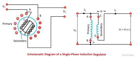
Single-phase Induction Voltage Regulator
The schematic diagram of the single phase induction voltage regulator is shown in the figure below. The primary winding is connected across the single phase supply, and the secondary is connected in series with the outgoing lines. The alternating flux is induced in the system and when the axis of the two windings coincide the whole of the flux of primary is linked with the secondary windings and the maximum voltage is induced in the secondary.
When the rotor is rotated through 90º, then none of the primary flux is linked with the secondary windings and hence no flux is linked with the secondary windings. If the rotor further rotates, then the direction of the induced emf becomes negative. Thus the regulator adds or subtracts the circuit voltage depends on the relative position of the two windings of regulators.
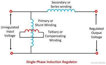
The single-phase voltage regulator does not cause any phase shift. The primary windings are placed in slots in the surface core of the laminated cylindrical core since it has to carry small currents and has small conductor area. The rotor of the regulator consists compensating windings also called the territory windings.
The magnetic axis of the compensating windings is always 90º away from that of the primary windings, to neutralise the harmful series reactance effect of the secondary. The secondary windings connected in series with the outgoing line are housed in the stator slots, due to its large conductor area.
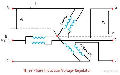
Three Phase Induction Voltage Regulator
The three phase induction motors have three primary and three secondary windings and which must be spaced 120º apart. The primary windings are placed in the slot of a laminated rotor core and connected across the three phase AC supply. The secondary windings are in slots of a laminated stator core and are connected in series with the load.
The regulator does not require any primary and compensating windings because the each secondary winding of the regulator is magnetically coupled to one or more primary winding of the regulator. In this regulator, the rotating magnetic field of constant magnitude is produced due to which the voltage induced in the secondary is of constant magnitude. The phases of the regulator vary with the change in the position of the rotor on the stator.

The phasor diagram of the induction regulator is shown in the figure above. Where V1 is the supply voltage, Vr is the induces voltage in the secondary and V2 is the output voltage per phase. The output voltage is obtained as the phasor sum of supply voltage and the induced voltage for any rotor displacement angle θ.
The locus of the circle is consequently a circle drawn with a centre on the edge of supply voltage and of radius Vr. The maximum output voltage is obtained when the induced voltage is in phase with the supply voltage, and the minimum output voltage is obtained when the induced voltage is in phase opposition with the supply voltage.
The complete phasor diagram for three phases is shown in the figure below.The A, B, and C are the input terminal and the a, b, and c are the output terminal of the induction regulator. The supply and the output line voltage are in phase only at maximum boost and minimum buck position, and for all other positions, there is the phase displacement between the supply line and the output voltage.
Good site.