Definition: The relay whose working depends on the distance between the impedance of the faulty section and the position on which relay installed is known as the impedance relay or distance relay. It is a voltage controlled equipment.
The relay measures the impedance of the faulty point, if the impedance is less than the impedance of the relay setting, it gives the tripping command to the circuit breaker for closing their contacts. The impedance relay continuously monitors the line current and voltage flows through the CT and PT respectively. If the ratio of voltage and current is less than the relay starts operating then the relay starts operating.
Principle of Operation of Impedance Relay
In the normal operating condition, the value of the line voltage is more than the current. But when the fault occurs on the line the magnitude of the current rises and the voltage becomes less. The line current is inversely proportional to the impedance of the transmission line. Thus, the impedance decreases because of which the impedance relay starts operating.
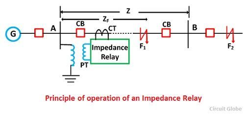
The figure below explains the impedance relay in much easier way. The potential transformer supplies the voltage to the transmission line and the current flows because of the current transformer. The current transformer is connected in series with the circuit.
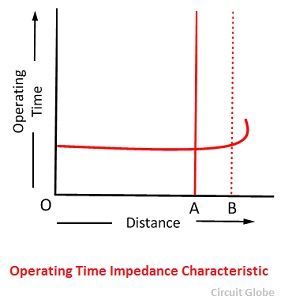
Consider the impedance relay is placed on the transmission line for the protection of the line AB. The Z is the impedance of the line in normal operating condition. If the impedances of the line fall below the impedance Z then the relay starts working.
Let, the fault F1 occur in the line AB. This fault decreases the impedance of the line below the relay setting impedance. The relay starts operating, and its send the tripping command to the circuit breaker. If the fault reached beyond the protective zone, the contacts of the relay remain unclosed.
Operating Characteristic of an Impedance Relay
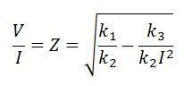
The voltage and the current operating elements are the two important component of the impedance relay. The current operating element generates the deflecting torque while the voltage storage element generates the restoring torque. The torque equation of the relay is shown in the figure below
![]()
The -K3 is the spring effect of the relay. The V and I are the value of the voltage and current. When the relay is in normal operating condition, then the net torque of the relay becomes zero.
![]()
If the spring control effect becomes neglected, the equation becomes
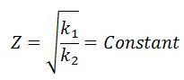
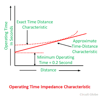
The operating characteristic concerning the voltage and current is shown in the figure below. The dashed line in the image represents the operating condition at the constant line impedance.
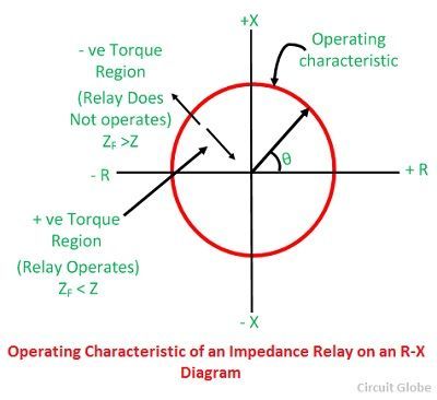
The operating characteristic of the impedance relay is shown in the figure below. The positive torque region of the impedance relay is above the operating characteristic line. In positive torque region, the impedance of the line is more than the impedance of the faulty section. Similarly, in negative region, the impedance of the faulty section is more than the line impedance
 The impedance of the line is represented by the radius of the circle. The phase angle between the X and R axis represents the position of the vector. If the impedance of the line is less than the radius of the circle, then it shows the positive torque region. If the impedance is greater than the negative region, then it represents the negative torque region.
 This type of relay is called the high-speed relay.
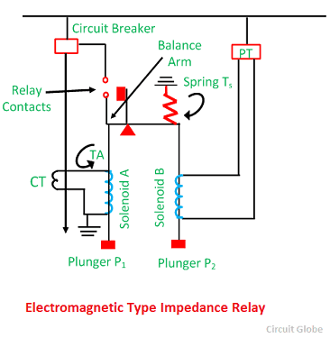
Electromagnetic Type Induction Relay
In such type of relay, the torque is induced by the electromagnetic action on the voltage and current. These torques are compared. Consider the circuit of the electromagnetic type induction relay. The solenoid B is excited by the voltage supplied of the PT. This voltage develops the torque in the clockwise direction, and it pulls the plunger P2 in the downward direction. The spring connects to the plunger P2 apply the restraining force on it. This spring generates the mechanical torque in the clockwise direction.
The solenoid A generates the other torque in the clockwise direction and thus moves the plunger P1 downwards. The solenoid one is excited by the CT of the lines. This torque is called the deflecting or pick up torque.
When the system is free from fault, the contacts of the relay become open. When the fault occurs in the protective zone, the current of the system rises because of which the current across the relay also increases. The more torque developed on the solenoid A. The restoring torque because of the voltage decreases. The balance arms of the relay start rotating in the opposite direction, thus closed their contacts.
 The pull of the solenoid A, i.e., (current element) is proportional to I2 and that due to solenoid B (voltage element) to V2. Consequently, the relay will operate when
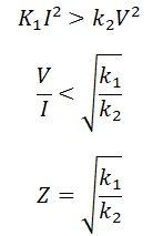 The value of the constants k1 and k2 depend on the ampere-turns of the two solenoids, and the ratios of the instrument transformers. By providing tappings on the coil, the setting of the relay can be changed.
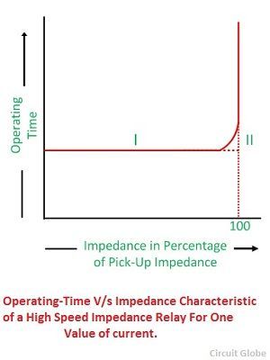
The y-axis shows the operating time of the relay and the X-axis represents their impedances. The operating time of the relay remains constants. The value of the voltage and current becomes constant at the predetermined distance and after that their value becomes infinite.
 Induction Type Impedance Relay
The circuit diagram of the induction type impedance relay is shown in the figure below. This relay consists current and voltage element. The relay has an aluminium disc, which is rotating between the electromagnets.
The upper electromagnet has two separate windings. The primary winding is connected to the secondary coil of the current transformer. The current setting of the winding is varied by the help of the plug bridge placed below the relay.
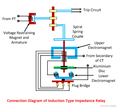
The electromagnetics of the relay connects in series with each other. The flux induce between the electromagnets produces the rotational torque, which rotates the aluminium disc of the relay. The permanent magnet provides the controlling and braking torque.
In normal operating conditions the force exerted on the armature is more than the induction element which keeps the trip contacts open. When the fault occurs in the system, then the aluminium disc starts rotating, and their rotation is directly proportional to the current of the electromagnet. The rotation of the disc-wound the spring.
The angle of the rotation of the disc for relay operation depends on the force acting on their armature. The force acting on the armature is directly proportional to the applied voltage. Thus, the angle of rotation also depends on the voltage.
Time-Characteristic of High-Speed Type Impedance Relay
The figure below shows that the relay does not operate for the value more than the 100 percent pickup value. The curves 1 is the actual characteristic, and the curve 2 is the simplified characteristic of the curve 1.
 Drawbacks of Plan Impedance Relay
The following are the disadvantages of the impedance relay.
- It gives the response on both the side of the CT and PT. Thus, it becomes difficult for the breaker to determine whether the fault is external or internal.
- The relay is easily affected by the arc resistance of the line.
- It is very sensitive to the power swing. The powerful wings generate the faults on the line because of which the impedances of the line vary.
The relay always operates when the impedance of the line is less than the relay settings.
The Impedance Type Distance Relay piece was very helpful.
Thanks a lot!
A very good description thank you.
Nice explanation☺