Definition: In dual trace oscilloscope, a single electron beam generates 2 traces, that undergoes deflection by two independent sources. In order to produce two separate traces, basically, 2 methods are used, known as alternate and chopped mode.
These are also known as the two operating modes of the switch.
Now the question arises what is the need for such an oscilloscope?
So, we know to analyse or study multiple electronic circuits, the comparison between their voltages is really important. Hence to compare the different circuits, one can use multiple oscilloscopes.
But simultaneously triggering the sweep of each oscilloscope is a quite difficult task.
Thus we have used dual trace oscilloscope provides two traces by making use of a single electron beam.
Block diagram and Working of Dual Trace Oscilloscope
The figure below shows the block diagram of a dual trace oscilloscope:
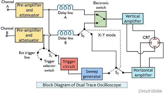
As we can see in the above figure that it has two individual vertical input channels namely A and B.
Both the inputs are separately fed to the preamplifier and attenuator stage. The outputs of the two separate preamplifiers and attenuator stage are then provided to the electronic switch. This switch only passes a single channel input particularly at a time to the vertical amplifier.
The circuit also has a trigger selector switch that permits the circuit triggering with either A or B channel input or with the externally applied signal.
The signal from the horizontal amplifier is fed to the electronic switch by either sweep generator or channel B by switch S0 and S2.
In this way, the vertical signal from channel A and horizontal signal from channel B is provided to the CRT for the operation of the oscilloscope.
This is the X-Y mode of the oscilloscope and permits accurate X-Y measurements.
Basically, the modes of operation of the oscilloscope rely on the choice of front panel controls. Like either the trace of channel A is needed, channel B is needed or separately trace of channel A or B is required.
As we have already discussed that there exist two modes of operation of dual trace oscilloscope.
Let us have a look at both the methods separately.
Alternate mode of Dual Trace Oscilloscope
Whenever we activate the alternate mode, then it permits the connection between both the channels alternately. This alternation or switching between the channels A and B takes place at the beginning of each upcoming sweep.
Also, there exists synchronization between the switching rate and the sweep rate. This leads to the spotting of traces of each channel on one sweep. Like in first sweep traces of channel A will be spotted, then in the next sweep traces of channel B will be considered by the CRT.
In this way, the alternate connection of the two-channel input with the vertical amplifier is performed.
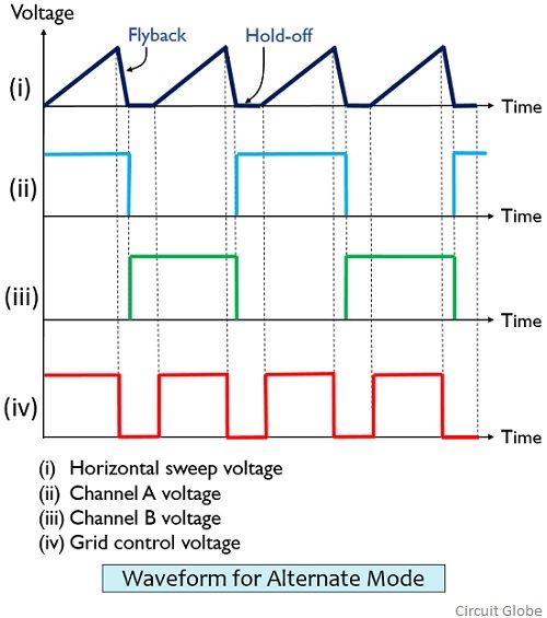
The change in the electronic switch from one channel to the other occurs at fly back sweep duration. At the flyback period, the electron beam will be invisible and so the changeover from one channel to other.
Hence a complete sweep signal from one vertical channel will be displayed at the screen. While for the next sweep, the signal from another vertical channel will be displayed.
The figure below represents the waveform the oscilloscope output operating in alternate mode:
This method allows us to maintain the proper phase relationship between signals of channel A and B. However, along with advantage, a disadvantageous factor is also associated with this mode.
Alternate mode leads to a display that will show the occurrence of both the signals at different time. But in actual practice, the two events occur simultaneously. Also, the method cannot be used for the representation of the low-frequency signal.
Chopped mode of Dual Trace Oscilloscope
In this mode of operation during a single sweep, several times switching between the two channels occurs. And this switching is so quick that even for the very small segment the display is available at the screen.
The figure below shows the waveform representation in case of chopped mode:
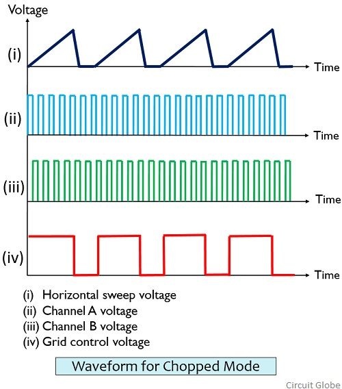
Here, the electronic switch undergoes free running at a very high frequency of about 100 KHz to 500 KHz. And the frequency of electronic switch does not rely on the frequency of the sweep generator.
Hence in this way, the small segments of the two channels get connected to the amplifier in a continuous manner.
When the chopping rate is faster than the rate of horizontal sweep, then the separately chopped segments will be merged and recombine to form originally applied channel A and B waveform at the screen of CRT.
However, if the chopping rate is lesser than the sweep rate then it will definitely lead to discontinuity in the display. Therefore, in such case alternate mode is more suitable.
The dual trace oscillator permits the choice of respective mode of operation through the front panel of the instrument.
How can I set up to check my three phase power system for a balanced mode of operation?
Great