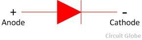
Diodes are the electronic components devices which allow the current to flow more easily and smoothly through any device in a particular direction. It has two electrodes, one is known as Anode, and the other one is Cathode. Semiconductor materials like Silicon and Germanium are used for the manufacturing of the diodes.
 Uses of Diodes
The diodes are used for various purposes such as:
- Rectifier
- Voltage Regulator
- Switches
- Oscillators
- Signal limiters, modulators and demodulators.
There are a large number of semiconductor diodes of different ratings which are used in electronic circuits as per the requirement. The diodes are of different shapes, sizes and colours.
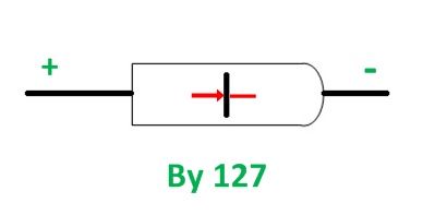
The figure below shows the shape of BY 127 diode which can carry 1 Ampere forward current with Peak Inverse voltage of 1000 V safely. It is green in colour and the direction in which it can conduct is marked by the symbol as shown in the figure. In the same series, there are also other diodes like BY 118 etc.
 The figure below shows the shape of a 1N 4007 diode:
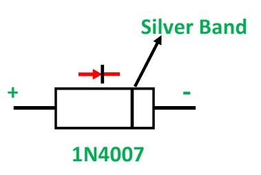 It can carry 1 A forward current with PIV of 100 V safely. It is black in colour. On one side a silver colour band is printed which shows the negative end (cathode) of the diode. In the same series, the other diodes are 1N 4001, 1N 4002. 1N 4003, 1N 4004, etc. Another diode of the same series is 1N 5406 which can carry 6A current with PIV of 200 V.
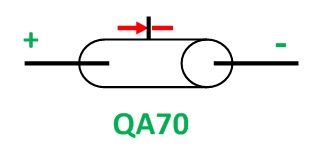
The figure below shows the shape of OA 79 diode. It is made of transparent glass. A Red mark on the body (arrow) denotes the positive terminal. The other diode of the same series is OA 80, OA 85, etc.
The figure below shows the shape of the power diode D 1604 N. It has a metallic body and can handle large power. It can carry 16 A current with PIV of 400 V safely. Another power diode is 10 KLR 12 which can carry 10 A current at PIV of 1200 V.
 Checking of Diode Terminals
If a symbol or mark on the body of a diode showing its terminal polarity is missing or rubbed off, then the terminal’s polarity can be determined with the help of an Ohm Meter or Multimeter.
The figure below shows that the polarity of the terminals of the battery contained within an ohmmeter appears on the leads of the Ohm Meter.
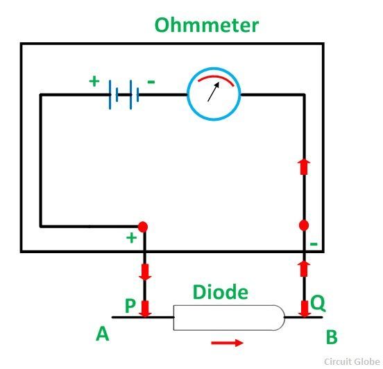 Lead P is positive, and the Q is negative. To check the terminal of the diode, it is connected to the leads P and Q as shown in the above figure. If the diode conducts and the meter gives deflection, then the terminal A of the diode is positive (anode) and B is negative (cathode).
However, if the diode does not conduct and there is no deflection in the Ohm Meter, the terminals of the diode are opposite as before.