A stationary generator must not be connected to live Busbars because the induced EMF is zero at standstill resulting in a short circuit. The Synchronisation procedure and the equipment for checking it are the same whether one alternator is to be connected in parallel with another alternator, or an alternator is to be connected to the infinite bus.
Contents:
- Synchronisation by Synchronising lamps
- Advantages of the Dark Lamp Method
- Disadvantages of the Dark Lamp Method
- Three Bright Lamp Method
- Two Bright One Dark Lamp Method
The following methods are used for synchronization.
Synchronisation by Synchronising lamps
A set of three synchronizing lamps can be used to check the conditions for paralleling or synchronization of the incoming machine with the other machine. A dark lamp method along with a voltmeter used for synchronizing is shown below. This method is used for low-power machines.
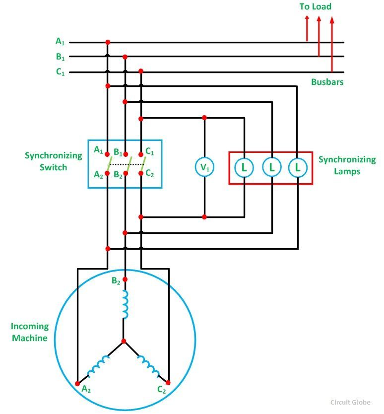
The prime mover of the incoming machine is started and brought nearer to its rated speed. A field current of the incoming machine is adjusted in such a way so that it becomes equal to the bus voltage. The flicker of the three lamps occurs at a rate that is equal to the difference in the frequencies of the incoming machine and the bus. All the lamps will glow and off at the same time if the phases are properly connected. If this condition does not satisfy, then the phase sequence is not connected correctly.
Thus, in order to connect the machine in the correct phase sequence, two leads to the line of the incoming machine should be interchanged. The frequency of the incoming machine is adjusted until the lamp flicker at a slow rate. The flicker rate should be less than one dark period per second. After finally adjusting the incoming voltage, the synchronizing switch is closed in the middle of their dark period.
Advantages of the Dark Lamp Method
- This method is cheaper.
- The correct phase sequence is easily determined.
Disadvantages of the Dark Lamp Method
- The lamp becomes dark at about half of its rated voltage. Hence, it is possible that the synchronizing switch might be switched off even when there is a phase difference between the machine.
- The filament of the lamp might burn out.
- The flicker of the lamps does not indicate which lamp has the higher frequency.
Three Bright Lamp Method
In this method, the lamps are connected across the phases such as A1 is connected to B2, B1 is connected to C2, and C1 is connected to A2. If all the three lamps get bright and dark together, this means that the phase sequence is correct. The correct instant of closing the synchronizing switch is in the middle of the bright period.
Two Bright One Dark Lamp Method
In this method, one lamp is connected between corresponding phases while the two others are cross-connected between the other two phases as shown in the figure below:
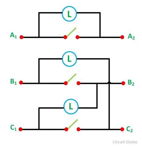
Here, A1 is connected to A2, B1 to C2, and C1 to B2. The prime mover of the incoming machine is started and brought up to its rated speed. The excitation of the incoming machine is adjusted in such a way that the incoming machine induces the voltage EA1, EB2, EC3, which is equal to the Busbar voltages VA1, VB1 and VC1. The diagram is shown below.
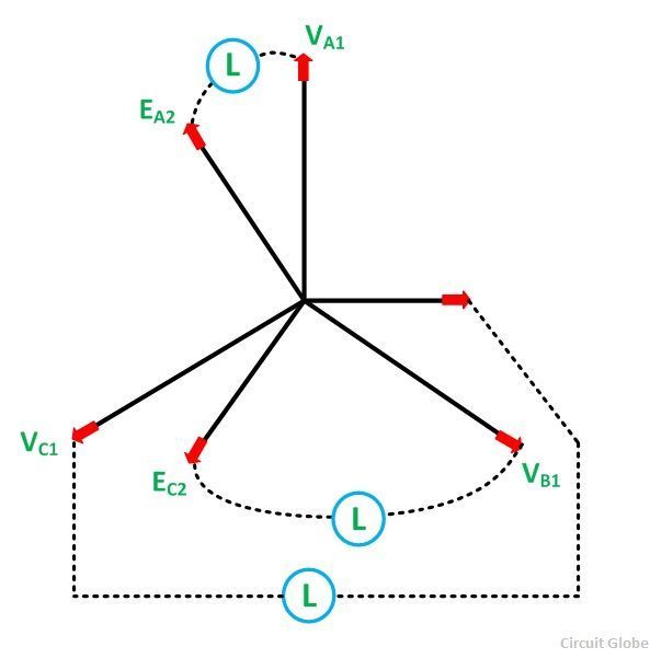
The correct moment to close the switch is obtained at the instant when the straight connected lamp is dark, and the connected cross lamps are equally bright. If the phase sequence is incorrect, no such instant will take place, and all the lamps will be dark simultaneously.
The direction of rotation of the incoming machine is changed by interchanging the two lines of the machine. Since the dark range of the lamp extends to a considerable voltage range, a voltmeter V1 is connected across the straight lamp. The synchronizing switch is closed when the voltmeter reading is zero.
Thus, the incoming machine is now floating on the Busbar and is ready to take up the load as a generator. If the prime mover is disconnected, it behaves as a motor. For paralleling small machines in power stations, three lamps along with the synchroscope are used. For synchronizing very large machines in power stations, the whole procedure is performed automatically by the computer.
Also See: Synchroscope Synchronizing
nice
Sir I want to make a project report on To design panel for synchronisation of alternator to infinite bus bar by dark lamp method pdf
Good One!!!
Hi
For a 3 phase circuit 220v what should be the voltage of every lamp?