As the armature rotates, a voltage is generated in its coils. In the case of a generator, the emf of rotation is called the Generated emf or Armature emf and is denoted as Er = Eg. In the case of a motor, the emf of rotation is known as Back emf or Counter emf and represented as Er = Eb.
The expression for emf is same for both the operations, i.e., for Generator as well as for Motor.
Derivation of EMF Equation of a DC Machine – Generator and Motor
Let,
- P – number of poles of the machine
- ϕ – Flux per pole in Weber.
- Z – Total number of armature conductors.
- N – Speed of armature in revolution per minute (r.p.m).
- A – number of parallel paths in the armature winding.
In one revolution of the armature, the flux cut by one conductor is given as:
![]()
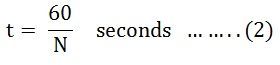
Time taken to complete one revolution is given as:
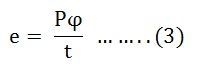
Therefore, the average induced e.m.f in one conductor will be:
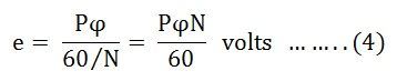
Putting the value of (t) from Equation (2) in the equation (3) we will get
The number of conductors connected in series in each parallel path = Z/A.
Therefore, the average induced e.m.f across each parallel path or the armature terminals is given by the equation shown below:
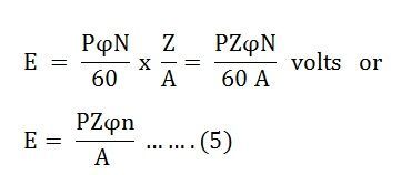
Where n is the speed in revolution per second (r.p.s) and given as:

For a given machine, the number of poles and the number of conductors per parallel path (Z/A) are constant. Hence, equation (5) can be written as:
![]()
Where K is a constant and given as:
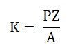
Therefore, the average induced emf equation can also be written as:
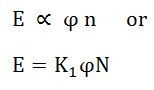
Where K1 is another constant and hence induced emf equation can be written as:
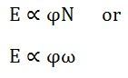
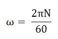
Where ω is the angular velocity in radians/second is represented as:
Thus, it is clear that the induced emf is directly proportional to the speed and flux per pole. The polarity of induced emf depends upon the direction of the magnetic field and the direction of rotation. If either of the two is reversed the polarity changes, but if two are reversed the polarity remains unchanged.
This induced emf is a fundamental phenomenon for all the DC Machines whether they are working as a generator or motor.
If the DC Machine is working as a Generator, the induced emf is given by the equation shown below:
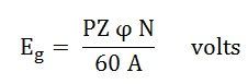
Where Eg is the Generated Emf
If the DC Machine is working as a Motor, the induced emf is given by the equation shown below:
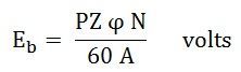
In a motor, the induced emf is called Back Emf (Eb) because it acts opposite to the supply voltage.
its very good
It is very good
Excellent explanation of back emf equation
Thank you
Very use full
Excellent explanation
Very much helpful. Thank u so much.
👍
good explanation
Very clear and understandable
Really it’s useful nice explanation Easy to understand step by step
Easy to understand and very helpful
Thanks for the clear explanation.
The site is best for students..
so wonderful
Very good explanation there are various points to learn
Nice. Thank you