Definition: A multiplier circuit that generates a dc output voltage having amplitude twice the maximum amplitude of the ac input supply voltage is known as Voltage Doubler. The circuit shows its necessity in all such applications where a high level of voltage is required when the input source is of low amplitude.
Here, the name itself is indicating that it generates a voltage having peak double as that of input at the output.
Voltage doubler circuits are mainly characterized as:

Let us first understand half-wave voltage doubler.
Half Wave Voltage Doubler
The figure below shows the circuit of half-wave voltage doubler:
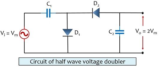
The circuit is made of two diodes D1 and D2, two capacitors C1 and C2 and an ac supply voltage. This input ac voltage gets doubled by the circuit and a double amplitude dc signal is achieved at the output.
Let us now understand how this happens:
When positive half of the input signal is applied, diode D1 gets forward biased. Due to this, it behaves as a short circuit and current flows through the diode. This current charges the capacitor C1 up to the peak value of the applied input signal.
At the same time, the positive half of the input signal reverse biases the diode D2. Due to this current does not flow through that portion of the circuit. Hence, C2 will not get charged.
Due to the absence of a return path for the current, the charge present in capacitor C1 will not get discharged. Hence, C1 stores the charge because of its energy storing property.
When negative half of the input signal is applied, diode D2 comes in forward biased although D1 falls in reversed biased.
Due to reverse the biased condition of D1, capacitor C1 will not get charged. However, the capacitor C1 will now discharge. While C2 charges due to forward biased condition of diode D2.
The capacitor C2 present in the circuit charges will gets charged but with double the peak of applied input voltage i.e., 2Vm. This is so because the discharging capacitor voltage of C1 and applied input voltage gets added.
Hence producing a voltage that is twice the peak of the applied input voltage i.e., 2Vm. Now, the charge present on the capacitor gets discharged through the load. Hence the dc output with the peak of 2Vm is achieved.
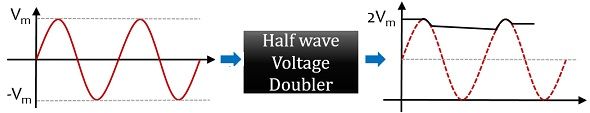
The thing that has to be kept in mind in case of half-wave voltage doubler is that the output does not increase rapidly. But with each applied input cycle it rises slowly.
Another factor is that simply one-half cycle charges the capacitor C2. Thus, the discharging voltage consists of ripple (unwanted fluctuations) frequency that is equivalent to supply frequency of applied input signal.
The figure below shows the input and output waveform of half-wave voltage doubler:
Let us now understand full wave voltage doubler.
Full Wave Voltage Doubler
The figure below shows the circuit of full wave voltage doubler:
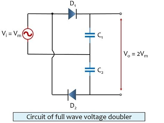
The circuit has an ac source, two capacitors C1 and C2 and two diodes D1 and D2.
Let us have a look at the operation of the circuit:
When positive half of supply is provided, the diode D1 gets forward biased. This forward voltage charges the capacitor C1 up to the maximum value of applied input voltage Vm.
At this particular cycle, D2 gets reverse biased, causing no any current to flow through it. Hence, capacitor C2 will not be charged.
When the negative half cycle of the signal is applied, the diode D2 will be forward biased. However, D1 will now come to reverse biased state. Due to forward biasing applied at D2, the current flowing through the circuit will charge capacitor C2 up to Vm. However, capacitor C1 will not be charged this time due to reverse biasing of D1.
As the two capacitors form a series connection. Thus, the output achieved will be Vm + Vm i.e., 2Vm. However, in the presence of a load, this output will be a little bit less than a no-load condition (2Vm).
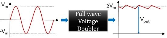
The figure below shows the input and output waveform of full wave voltage doubler:
Advantages of Voltage Doubler
- It eliminates the use of a high voltage transformer. As it changes a low voltage to high at a low rate.
- Voltage multiplication can be greatly increased by cascading such circuits.
Disadvantages of Voltage Doubler
- The output present has undesired fluctuations called ripples.
Applications of Voltage Doubler
Voltage doublers are used widely in cathode ray tubes, in x-ray and radar systems along with LCD backlight, in laser systems and in oscilloscopes etc.
very useful information thanks…
Thankyou_for_information_it_is_really_helpfull_thankyou😊