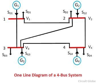
In a power system, power is injected into a bus from generators, while the loads are tapped from it. There may be some buses with only generators and there may be other only with loads. Some buses have generators and loads while some other may have static capacitors for reactive power compensation. The surplus power at some of the buses is transported through transmission lines to the bus deficient in power.
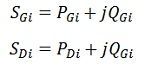
Single line diagram of a simple 4-bus system with generators and load at an each bus is shown in the figure. Let SGi denote the 3-phase complex generator power flowing into the ith bus and SDi denotes the 3-phase complex power demand at the ith bus. Let SGi and SDi may be represented as
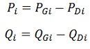
 Net complex power injected into the bus is given as
![]() The real and reactive power injected into the ith bus are then.
The real and reactive power injected into the ith bus are then.
 where i = 1, 2, 3, 4, ……..n.
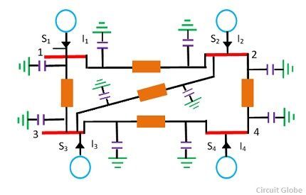
 A network model of the given power system worked out on the above line is shown below in the figure. S1, S2, S3, S4 denote the net 3-phase complex power flowing into the buses and I1, I2, I3, I4 denotes the current flowing into the buses. Each transmission line is represented by a π-circuit.
The equivalent circuit of 4-bus system is shown in the figure below. All the sources of the bus system connected to the common reference at ground potential and the shunt admittance at the busses have been lumped. Besides the ground node, it has four other nodes or buses at which the current from the source is injected into the network. The line admittance between nodes i and k is represented by yik = yki. Further, the mutual admittance between lines is assumed to be zero.
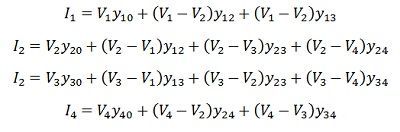
 Applications of Kirchhoff’s current law to the four nodes gives the following equation.
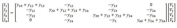
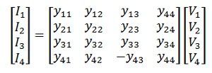
 The above equation can be rearranged and written in matrix form as below.
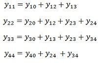
 The self-admittance terms of the matrix are given as
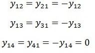
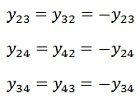
 The mutual admittances of the matrix are given as
 Matrix is written in terms of self-bus admittance Yi and mutual bus admittance Yik as follows.
 Yii is known as self-admittance ( or driving point admittance ) of the ith node and is equal to the sum of the admittance connected to the ith node. Each off-diagonal term Yik is known as mutual admittance (or transfer admittance ) between ith and kth node and is equal to the negative of the sum of all the admittances connected directly between ith and kth node
The equation can be written in compact form as
![]() Where I is the current node matrix, V is the node voltage matrix and [ Ybus ] is the bus admittance matrix. General equation for n-bus network based on Kirchoff’s’ current law and admittance form is
Where I is the current node matrix, V is the node voltage matrix and [ Ybus ] is the bus admittance matrix. General equation for n-bus network based on Kirchoff’s’ current law and admittance form is
![]() where [ I ] is the n-bus matrix, [ V ] is the n-bus voltage matrix and, [ Ybus ] is called bus admittance matrix and is written as
where [ I ] is the n-bus matrix, [ V ] is the n-bus voltage matrix and, [ Ybus ] is called bus admittance matrix and is written as
![]()
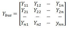 and is called the bus admittance matrix and V and I are the n-element node voltage matrix and current node matrix respectively.