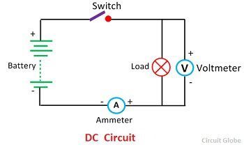
Definition: The closed path in which the direct current flows is called the DC circuit. The current flows in only one direction and it is mostly used in low voltage applications. The resistor is the main component of the DC circuit.
A simple DC circuit is shown in the figure below which contains a DC source (battery), a load lamp, a switch, connecting leads, and measuring instruments like ammeter and voltmeter.The load resistor is connected in series, parallel or series-parallel combination as per requirement.
 Types of DC Circuit
The DC electric circuit is mainly classified into three groups. They are the series DC circuit, parallel DC circuit, and series and parallel DC circuit.
DC Series Circuit
The circuit in which have DC series source, and the number of resistors are connected end to end so that same current flow through them is called a DC series circuit. The figure below shows the simple series circuit. In the series circuit the resistor R1, R2, and R3 are connected in series across a supply voltage of V volts. The same current I is flowing through all the three resistors.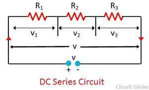 If V1, V2, and V3 are the voltage drop across the three resistor R1, R2, and R3 respectively, then
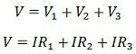 Let R be the total resistance of the circuit then,
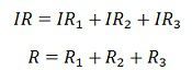 Total resistance = Sum of the individual resistance.
In such type of circuit all the lamps are controlled by the single switch and they cannot be controlled individually.The most common application of this circuit is for decoration purpose where a number of low voltage lamps are connected in series.
DC Parallel Circuit
The circuit which have DC source and one end of all the resistors is joined to a common point and other end are also joined to another common point so that current flows through them is called a DC parallel circuit.
The figure shows a simple parallel circuit. In this circuit the three resistor R1, R2, and R3 are connected in parallel across a supply voltage of V volts. The current flowing through them is I1, I2 and I3 respectively.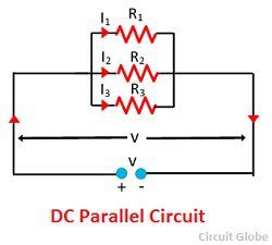 The total current drawn by the circuit
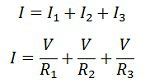 Let R be the total or effective resistance of the circuit, then
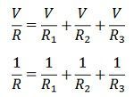 Reciprocal of total resistance = sum of reciprocal of the individual resistance..
All the resistance is operated to the same voltage, therefore all of them are connected in parallel. Each of them can be controlled individually with the help of a separate switch.
DC Series-Parallel Circuit
The circuit in which series and parallel circuit are connected in series is called a series parallel circuit.The figure below show the series-parallel circuit. In this circuit, two resistor R1 and R2 are connected in parallel with each other across terminal AB. The other three resistors R3, R4 and R6 are connected in parallel with each other across terminal BC.
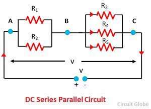 The two groups of resistor RAB and RBC are connected in series with each other across the supply voltage of V volts. The total or effective resistance of the whole circuit can be determined as given below
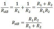 Similarly,
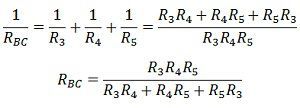 Total or effective resistance of the ciruit,
![]() Also see: AC Circuit
Also see: AC Circuit
Good info
Really nice info