Amplidyne is the most common version of the Metadyne. It consists of the basic metadyne in which a compensating winding is connected in series with the power output brush terminals. The compensating winding cancels out the d axis MMF, which opposes the control field MMF.
The schematic diagram of the Amplidyne is shown below.
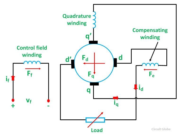
The compensating winding is located in the direct (d axis) on the stator. This compensating winding carries the load current id. The winding produces a flux which opposes the flux produced by the direct axis armature current. The effect of the negative feedback of the load current is minimized. The d axis flux now depends on the field winding current.
The degree of compensation C is defined as the ratio of effective compensating winding turns to the effective armature turns.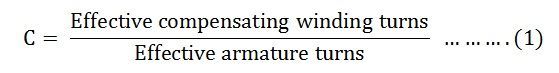
The effect of degree of compensation on the load characteristic of a cross field machine is shown below.
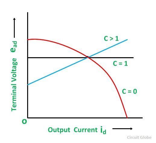
In case of the Metadyne, there is no compensating winging thus, the value of C = 0. In Amplidyne full compensation exists and hence, C = 1. The terminal voltage of an Amplidyne is considered almost constant. The power amplification (eadid/efif) is of the order of 105 as compared to 100 for a direct current generator.
A series connected quadrature axis (q axis) winding is placed on the stator of the amplidyne to improve its performance and, as a result, quadrature (q axis) commutation also improves. They were used before the origin of high power, high speed of response of solid state power amplifier and control equipment.
They were used to supply DC power to process control motors, excitation systems of large AC generators and Ward Leonard speed control systems. They are now replaced by the solid state power amplifiers.