Power in 3 Phase Circuits
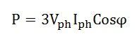
The three-phase power is mainly used for generation, transmission and distribution of electrical power because of their superiority. It is more economical as compared to single-phase power and requires three live conductors for power supply. Power in a single-phase system or circuit is given by the relation shown below:
![]()
Where,
V is the voltage of single-phase, i.e. Vph
I is the current of single-phase, i.e. Iph and
Cosϕ is the power factor of the circuit.
Contents:
In 3 phase circuits (balanced load), the power is defined as the sum of various powers in a three-phase system. i.e.
Power in star connections in a 3 phase circuits is given as
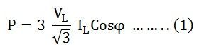
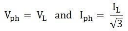
The phase voltage and line voltage in the star connection is represented as shown below:
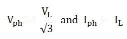
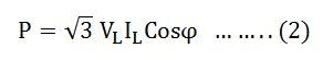
Therefore, equation (1) can be written as:
Power in delta connections in 3 phase circuits is given by the equation shown below:
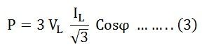
In delta connections, the relation between phase and line voltage and phase and line current is given as:
Hence, equation (3) can be written as

Thus, the total power in a 3 phase balanced load system, irrespective of their connections, whether the system is star connected or delta connected, the power is given by the relation:
√3 VLILCosϕ
Its units are kilowatt (kW) or Watt (W).
Apparent Power is given as:
![]()
The unit of apparent power is kilovolt-ampere (kVA) or volt-ampere (VA).
Similarly, Reactive Power is given by the equation:
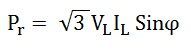
Its units are kilovolt-ampere reactive (kVAR) or volt-ampere reactive (VAR).
Generation of 3 Phase E.M.Fs in a 3 Phase Circuit
In a 3 phase system, there are three equal voltages or EMFs of the same frequency having a phase difference of 120 degrees. These voltages can be produced by a three-phase AC generator having three identical windings displaced apart from each other by 120 degrees electrical.
When these windings are kept stationary, and the magnetic field is rotated as shown in the figure A below or when the windings are kept stationary, and the magnetic field is rotated as shown below in figure B, an emf is induced in each winding. The magnitude and frequency of these EMFs are the same but are displaced apart from one another by an angle of 120 degrees.
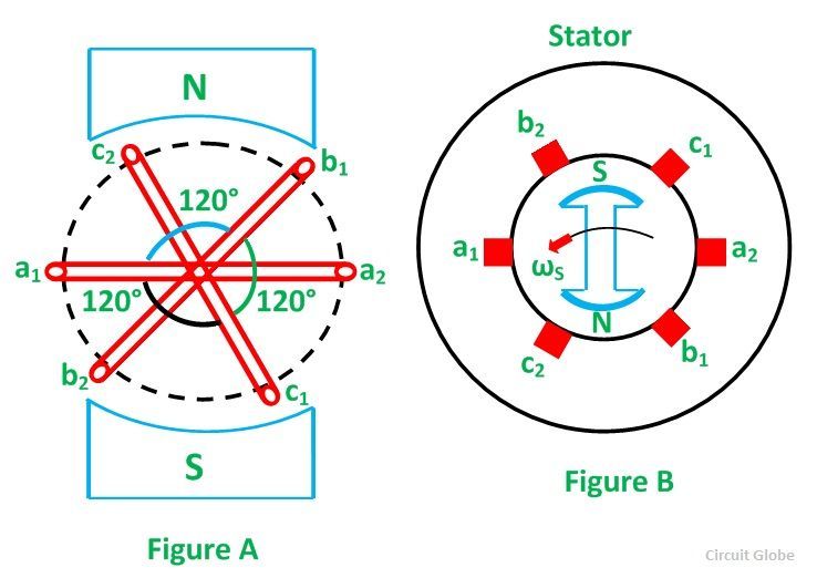 Consider three identical coils a1a2, b1b2 and c1c2 as shown in the above figure. In this figure a1, b1 and c1 are the starting terminals, whereas a2, b2 and c2 are the finish terminals of the three coils. The phase difference of 120 degrees has to be maintained between the start terminals a1, b1 and c1.
Now, let the three coils mounted on the same axis, and they are rotated by either keeping coil stationary and moving the magnetic field or vice versa in an anticlockwise direction at (ω) radians per seconds. Three EMFs are induced in the three coils respectively.
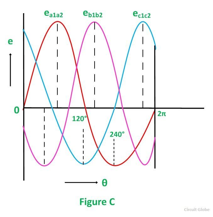 Considering the figure C, the analysis of their magnitudes and directions are given as follows:
The emf induced in the coil a1a2 is zero and is increasing in the positive direction as shown by the waveform in the above figure C represented as ea1a2.
The coil b1b2 is 120 degrees electrically behind the coil a1a2. The emf induced in this coil is negative and is becoming maximum negative as shown by the wave eb1b2.
Similarly, the coil c1c2 is 120 degrees electrically behind the coil b1b2, or we can also say that the coil c1c2 is 240 degrees behind the coil a1a2. The emf induced in the coil is positive and is decreasing as shown in figure C represented by the waveform ec1c2.
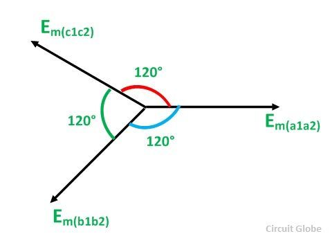
The EMFs induced in the three coils in 3 phase circuits are of the same magnitude and frequency and are displaced by an angle of 120 degrees from each other as shown below in the phasor diagram:
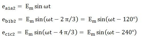
 These EMFs of 3 phase circuits can be expressed in the form of the various equations given below:
This is all about Generation of 3 Phase Power in 3 Phase Circuits.
Short nd simple answer
Awesome
Awesome