Definition: The cathode ray oscilloscope (CRO) is a type of electrical instrument which is used for showing the measurement and analysis of waveforms and others electronic and electrical phenomenon. It is a very fast X-Y plotter shows the input signal versus another signal or versus time. The CROs are used to analyse the waveforms, transient, phenomena, and other time-varying quantities from a very low-frequency range to the radio frequencies.
The CRO is mainly operated on voltages. Thus, the other physical quantity like current, strain, acceleration, pressure, are converted into the voltage with the help of the transducer and thus represent on a CRO. It is also used for knowing the waveforms, transient phenomenon, and other time-varying quantity from a very low-frequency range to the radio frequencies.
The CRO has Stylus (i.e., a luminous spot) which move over the display area in response to an input voltage. This luminous spot is produced by a beam of electrons striking on a fluorescent screen. The normal form of the CRO uses a horizontal input voltage which is an internally generated ramp voltage called “time base”.
The horizontal voltage moves the luminous spot periodically in a horizontal direction from left to right over the display area or screen. The vertical voltage is the voltage under investigation. The vertical voltage moves the luminous spot up and down on the screen. When the input voltage moves very fast on the screen, the display on the screen appears stationary. Thus, CRO provides a means of the visualising time-varying voltage.
Construction of Cathode Ray Oscilloscope
The main parts of the cathode ray oscilloscope are as follows.
- Cathode Ray Tube
- Electronic Gun Assembly
- Deflecting Plate
- Fluorescent Screen For CRT
- Glass Envelop
Their parts are explained below in details.
1. Cathode Ray Tube
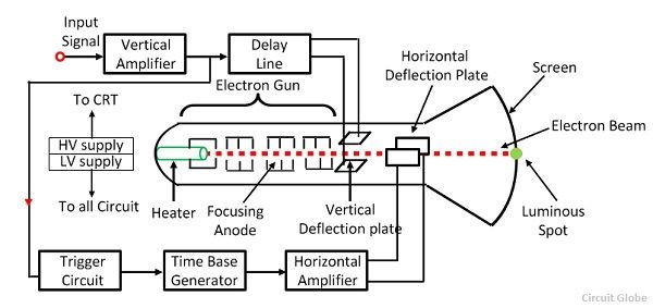
The cathode ray tube is the vacuum tube which converts the electrical signal into the visual signal. The cathode ray tube mainly consists the electron gun and the electrostatic deflection plates (vertical and horizontal).The electron gun produces a focused beam of the electron which is accelerated to high frequency.
The vertical deflection plate moves the beams up and down and the horizontal beam moved the electrons beams left to right. These movements are independent to each other and hence the beam may be positioned anywhere on the screen.
2. Electronic Gun Assembly
The electron gun emits the electrons and forms them into a beam. The electron gun mainly consists a heater, cathode, a grid, a pre-accelerating anode, a focusing anode and an accelerating anode. For gaining the high emission of electrons at the moderate temperature, the layers of barium and strontium is deposited on the end of the cathode.
After the emission of an electron from the cathode grid, it passes through the control grid. The control grid is usually a nickel cylinder with a centrally located co-axial with the CRT axis. It controls the intensity of the emitted electron from the cathode.
The electron while passing through the control grid is accelerated by a high positive potential which is applied to the pre-accelerating or accelerating nodes.
The electron beam is focused on focusing electrodes and then passes through the vertical and horizontal deflection plates and then goes on to the fluorescent lamp. The pre-accelerating and accelerating anode are connected to 1500v, and the focusing electrode is connected to 500 v. There are two methods of focusing on the electron beam. These methods are
- Electrostatic focusing
- Electromagnetic focusing.
The CRO uses an electrostatic focusing tube.
3. Deflecting Plate
The electron beam after leaving the electron gun passes through the two pairs of the deflecting plate. The pair of plate producing the vertical deflection is called a vertical deflecting plate or Y plates, and the pair of the plate which is used for horizontal deflection is called horizontal deflection plate or X plates.
4. Fluorescent Screen for CRT
The front of the CRT is called the face plate. It is flat for screen sized up to about 100mm×100mm. The screen of the CRT is slightly curved for larger displays. The face plate is formed by pressing the molten glass into a mould and then annealing it.
The inside surface of the faceplate is coated with phosphor crystal. The phosphor converts electrical energy into light energy. When an electronics beam strike phosphor crystal, it raises their energy level and hence light is emitted during phosphorous crystallisation. This phenomenon is called fluorescence.
5. Glass Envelope
It is a highly evacuated conical shape structure. The inner surface of the CRT between the neck and the screen is coated with the aquadag. The aquadag is a conducting material and act as a high-voltage electrode. The coating surface is electrically connected to the accelerating anode and hence help the electron to be the focus.
Working of Cathode Ray Oscilloscope
When the electron is injected through the electron gun, it passes through the control grid. The control grid controls the intensity of electron in the vacuum tube. If the control grid has high negative potential, then it allows only a few electrons to pass through it. Thus, the dim spot is produced on the lightning screen. If the negative potential on the control grid is low, then the bright spot is produced. Hence the intensity of light depends on the negative potential of the control grid.
 After moving the control grid the electron beam passing through the focusing and accelerating anodes. The accelerating anodes are at a high positive potential and hence they converge the beam at a point on the screen.
After moving from the accelerating anode, the beam comes under the effect of the deflecting plates. When the deflecting plate is at zero potential, the beam produces a spot at the centre.If the voltage is applied to the vertical deflecting plate, the electron beam focuses at the upward and when the voltage is applied horizontally the spot of light will be deflected horizontally.
thanks it was very helpful for me i am understand very clearly please always help me always to understand the things thank u
Useful content👍🔥
Sir.
In which concept CRO works?
wow so good explanation and easy to understand.. Thanks for this article be assured that it has been of help to me… Thumbs up for you 👍
You have provided grt theory and it helped me
Please, what are the advantages and the disadvantages of a cathode ray oscilloscope?
Thank you, for the valuable information.
It is very easy to understand the cro and also good explanation. Thanks for providing this Information.
Thanks a lot, it really helped ne me understanding the basic of this thing.
Please keep it up.
good job
thanks for this
Nice concept…
Super and excellent definition of CRO. It is very helpful for my Seminar. 😁Thank you, author.
This was really helpful to me. Thank you
Nice work!
It’s so helpful
Thanks